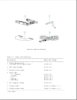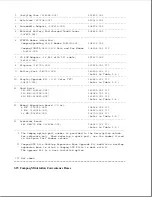
5. Display Cable
9.5 Inch Color TFT
149589-001 **
8.4 Inch Color TFT
149604-001
9.5 Inch Black and White TFT
197632-001
9.5 Inch Color STN
149737-001
10.4 Inch Color TFT
197909-001
8. Display Ground Cable
9.5 Inch Color TFT
149589-001 **
8.4 Inch Color TFT
197857-001
9.5 Inch Black and White TFT
194637-001 ***
9.5 Inch Color STN
194637-001 ***
10.4 Inch Color TFT
197937-001
9. Display Enclosure
9.5 Inch Color TFT
149589-001 **
8.4 Inch Color TFT
149596-001
9.5 Inch Black and White TFT
197664-001
9.5 Inch Color STN
149596-001
10.4 Inch Color TFT
197937-001
--------------------------------------------------------------------------
* Two display bezels are provided for the 9.5" color STN display. Use the
bezel that lines up property with the existing panel.
** The spare display panel, inverter board, display cable, display ground
cable, and display enclosure for the 9.5" color TFT display come
preinstalled in a display assembly to ensure compatibility and optimize
the display quality.
*** The ground cable used on the 9.5" black-and-white TFT and the 9.5"
color STN displays may be 2 inches shorter than the one used in the
other models. In addition, the shorter ground cable may not have a
ground clip inside the display enclosure.
===========================================================================
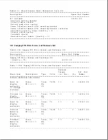
Common Display Parts
===========================================================================
Description
Spare Part Number
===========================================================================
2. Control Slide(s)
(Refer to Table 3-10.)
6. Trackball Board
149597-001
7. Clutches (left and right)
149592-001
10. Display Latches
(Refer to Table 3-8.)
*****
11. Compaq Display Logos ****
149605-001 *****
---------------------------------------------------------------------------
**** The Compaq display logos are also included with the display
enclosure.
***** Not Shown.
===========================================================================
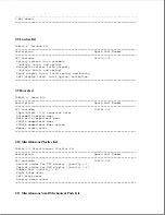
IMPORTANT: Each display type must use the exact panel, cable, inverter
board, and bezel that are listed above to ensure proper
performance.
Summary of Contents for LTE Elite
Page 140: ...7 Remove the hard drive security clips by gently lifting up on them Figure 4 32 ...
Page 248: ...4 Remove the keylock from the outside of the bottom cover Figure 9 5 ...
Page 249: ...5 Slide the plastic keylock barrel out of the bottom cover Figure 9 6 ...
Page 269: ...3 Disconnect the harness extension cable from the system board Figure 9 26 ...
Page 297: ...5 Slide the switch board out of the switch frame Figure 9 52 ...
Page 304: ...5 Replace the eject switch and screw Figure 9 59 ...
Page 309: ...5 Replace the power switch and screw Figure 9 64 ...
Page 348: ...7 Unlock the expansion base keylock Figure D 3 ...
Page 369: ...9 Push the lever toward the back of the convenience base Figure D 16 ...
Page 373: ...5 Slide the computer toward you to remove it from the convenience base ...
Page 387: ......


