background image


Appendix 

A


Regulatory Compliance Notices 

IMPORTANT:

  All of the following Regulatory Compliance Notices apply to the TX-based adapters and 

upgrade modules. For fiber adapters and fiber upgrade modules, only the European Union Notice applies. 

Federal Communications Commission Notice 

Part 15 of the Federal Communications Commission (FCC) Rules and Regulations has 

established Radio Frequency (RF) emission limits to provide an interference-free radio 

frequency spectrum. Many electronic devices, including computers, generate RF energy 

incidental to their intended function and are, therefore, covered by these rules. These rules 

place computers and related peripheral devices into two classes, A and B, depending upon 

their intended installation. Class A devices are those that may reasonably be expected to be 

installed in a business or commercial environment. Class B devices are those that may 

reasonably be expected to be installed in a residential environment (i.e., personal computers). 

The FCC requires devices in both classes to bear a label indicating the interference potential of 

the device as well as additional operating instructions for the user. 

The rating label on the device shows which class (A or B) the equipment falls into. Class B 

devices have an FCC logo or FCC ID on the label. Class A devices do not have an FCC logo 

or FCC ID on the label. Once the class of the device is determined, refer to the following 

corresponding statement. 

Class A Equipment 

This equipment has been tested and found to comply with the limits for a Class A digital device, 

pursuant to Part 15 of the FCC Rules. These limits are designed to provide reasonable protection 

against harmful interference when the equipment is operated in a commercial environment. This 

equipment generates, uses, and can radiate radio frequency energy and, if not installed and used 

in accordance with the instructions, may cause harmful interference to radio communications. 

Operation of this equipment in a residential area is likely to cause harmful interference, in which 

case the user will be required to correct the interference at personal expense. 


Summary of Contents for NC3134

Page 1: ...NC3134 Fast Ethernet Server Adapter User Guide Third Edition June 2007 Part Number 174846 00F Compaq Computer Corporation ...

Page 2: ...tes and other countries All other product names mentioned herein may be trademarks of their respective companies Compaq shall not be liable for technical or editorial errors or omissions contained herein The information in this document is provided as is without warranty of any kind and is subject to change without notice The warranties for Compaq products are set forth in the express limited warr...

Page 3: ...recautions 2 1 Attaching the Upgrade Module 2 2 Removing the Adapter from a Server 2 2 Installing the Upgrade Module on the Adapter 2 2 Installing the Adapter in a Server 2 4 Connecting the Network Cable 2 5 Connecting UTP Network Cable 2 5 Connecting Fiber Network Cable 2 5 Connecting and Using Loop Back Plugs 2 6 RJ 45 Loop Back Plug 2 6 Appendix A Regulatory Compliance Notices Federal Communica...

Page 4: ... C 2 NC3135 10 100 Upgrade Module C 2 NC6132 1000BASE SX Upgrade Module C 3 NC6133 1000BASE LX Upgrade Module C 3 NC3133 100BASE FX Upgrade Module C 3 NC7132 1000BASE T Gigabit over Copper Upgrade Module C 4 UTP Cable Specifications C 4 Using UTP Category 5 Cable in Gigabit over Copper Installations C 4 RJ 45 Pinouts and Crossover Function C 5 10 100 Straight Through Pinouts C 5 10 100 Crossover P...

Page 5: ... knowledgeable of the procedures precautions and hazards associated with equipment containing hazardous energy circuits Symbols in Text These symbols may be found in the text of this guide They have the following meanings WARNING Text set off in this manner indicates that failure to follow directions in the warning could result in bodily harm or loss of life CAUTION Text set off in this manner ind...

Page 6: ...te conditions that are hazardous WARNING To reduce the risk of electric shock or damage to the equipment If the system has multiple power supplies disconnect power from the system by unplugging all power cords from the power supplies Do not disable the power cord grounding plug The grounding plug is an important safety feature Plug the power cord into a grounded earthed electrical outlet that is e...

Page 7: ... Compaq Web based support services visit http www compaq com support Navigate to a specific product and then look for support information from this list of support resources For a complete list of available SoftPaq files navigate to http www compaq com support files allsp html Send email to support compaq com PaqFax Number The Compaq fax on demand retrieval system provides product specific informa...

Page 8: ... add in cards in your server The amount of memory in your server North America The Compaq Customer Support department for North America can be reached at 1 800 652 6672 1 800 OKCOMPAQ For continuous quality improvement calls may be monitored or recorded Europe the Middle East and Africa In Europe the Middle East and Africa contact your local Compaq authorized service provider Details of your local...

Page 9: ...apter has one RJ 45 connector and a 10 100 1000 Mb s port that delivers up to 1000 Mb s Ethernet over twisted pair cabling Gigabit over copper Table 1 1 describes the adapter and upgrade modules Table 1 1 NC3134 Adapter and Upgrade Modules with Port and Connection Options Name Type Number and Types of Ports Connection Option NC3134 Server adapter Two RJ 45 10BASE T 100BASE TX NC3133 Upgrade module...

Page 10: ...ith two fully integrated 10BASE T 100BASE TX networking chips The adapter contains a sophisticated 32 bit MAC with enhanced scatter gather and bus mastering capabilities Its true 32 bit architecture enables it to perform high speed data transfers on the PCI bus using four DMA channels It can process high level commands and perform multiple operations without processor intervention The NC3134 adapt...

Page 11: ...rade module has two RJ 45 dual speed ports and associated LEDs indicating link activity and speed Figure 1 2 NC3135 Upgrade Module 10 100 ports and LED indicators NC7132 Upgrade Module The NC7132 upgrade module has one RJ 45 auto negotiating tri speed port and associated LEDs indicating link activity and speed It supports UTP Gigabit over copper cabling Figure 1 3 NC7132 Gigabit over copper upgrad...

Page 12: ...LED color Table 1 2 10 100 LED Operations for the NC3134 Adapter and NC3135 Upgrade Module LED Display Description LNK On Amber The adapter is receiving power the cable connection between the hub switch and adapter is good and the link is established at 10 Mb s On Green The adapter is receiving power the cable connection between the hub switch and adapter is good and the link is established at 100...

Page 13: ...Blue The adapter is sending or receiving network data at 1000 Mb s Activity Speed Off The adapter is not sending or receiving network data Fiber Upgrade Module LED Indicators The fiber upgrade modules have two LEDs that indicate port operation as described below Table 1 4 Fiber Upgrade Module LED Operations for NC3133 NC6132 and NC6133 LED Display Description LNK On Green The adapter is receiving ...

Page 14: ... trained in the hazards associated with products capable of producing hazardous energy levels NOTE Before removing the cover of your server refer to the Compaq documentation for the proper method of installing a PCI card and safeguarding yourself from electrical shock hazards Electrostatic Discharge Precautions A discharge of static electricity from a finger or other conductor can damage component...

Page 15: ...tion on removing the adapter 1 If the server is not PCI Hot Plug compliant power down the server and unplug the power cord 2 Remove the server s cover WARNING To reduce the risk of personal injury from hot surfaces allow the internal system components to cool before touching them CAUTION If the server is not PCI Hot Plug compliant power it down and unplug the power cord from the power outlet befor...

Page 16: ...is flush with the lip of the hollow rivet Flanges on the hollow rivet expand to hold the extension bracket tightly to the adapter 7 Repeat steps 5 and 6 for the second rivet assembly NOTE To remove a rivet assembly 1 Use the blunt end of a small screwdriver to push the rivet pin about 1 8 inch out of the hollow rivet 2 Grasp the head of the rivet pin and pull it out of the hollow rivet This releas...

Page 17: ...e server and unplug the power cord 2 Remove both the server cover and the cover bracket from a PCI slot WARNING To reduce the risk of personal injury from hot surfaces allow the internal system components to cool before touching them CAUTION If the server is not PCI Hot Plug compliant power it down and unplug the power cord from the power outlet before removing the server cover Failure to do so ma...

Page 18: ...ver copper connections For new Gigabit over copper installations Category 5e enhanced Category 5 is recommended Note If you use the adapter in a residential environment you must use a Category 5 or better cable for both 10BASE T and 100BASE TX networks The UTP network connections on the adapter and upgrade modules are RJ 45 connectors To attach the cable plug the cable connector into the port When...

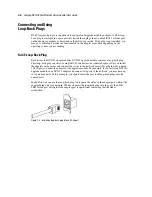
Page 19: ...p back plug consists of a single RJ 45 connector on a truncated cable After you install the adapters in the server and connect the server to the network insert this plug into any unused 10 100 ports on either the adapter or the upgrade module For example if you install an NC3135 upgrade module in an NC3134 adapter and connect two ports to the network you may have up to two unused ports In this exa...

Page 20: ...t i e personal computers The FCC requires devices in both classes to bear a label indicating the interference potential of the device as well as additional operating instructions for the user The rating label on the device shows which class A or B the equipment falls into Class B devices have an FCC logo or FCC ID on the label Class A devices do not have an FCC logo or FCC ID on the label Once the...

Page 21: ...he equipment into an outlet on a circuit different from that to which the receiver is connected Consult the dealer or an experienced radio or television technician for help Modifications The FCC requires the user to be notified that any changes or modifications made to this device that are not expressly approved by Compaq Computer Corporation may void the user s authority to operate the equipment ...

Page 22: ... de la classe B respecte toutes les exigences du Règlement sur le matériel brouilleur du Canada European Union Notice Products with the CE Marking comply with both the EMC Directive 89 336 EEC and the Low Voltage Directive 73 23 EEC issued by the Commission of the European Community Compliance with these directives implies conformity to the following European Norms in brackets are the equivalent i...

Page 23: ...A 4 Compaq NC3134 Fast Ethernet Server Adapter User Guide Japanese Notice ...

Page 24: ...ic sensitive component or assembly Grounding Methods There are several methods for grounding Use one or more of the following methods when handling or installing electrostatic sensitive parts Use a wrist strap connected by a ground cord to a grounded workstation or computer chassis Wrist straps are flexible straps with a minimum of 1 megohm 10 percent resistance in the ground cords To provide prop...

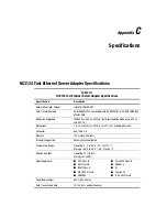
Page 25: ...figuration mode only 802 1p and 802 1Q Dimensions 7 4 x 5 0 inches L x W 18 8 cm x 12 7 cm including bracket Connector See Table C 8 Distance 100 meters 328 feet Interrupts Supported Automatically configured Temperature Range Operating 0 C to 55 C 32 F to 131 F Storage 65 C to 85 C 85 F to 185 F Relative Humidity Operating 10 to 90 Storage 5 to 95 Agency Approvals FCC Class B VCCI Class B BSMI Cla...

Page 26: ...oller Chipset Intel 82558 MAC PHY Standards Supported IEEE 802 3x 802 3u 802 1p and 802 1Q Connector and Distances See Table C 8 Dimensions 5 7 x 3 9 inches L x W 16 5 cm x 64 cm Agency Approvals See Table C 1 Power Requirements 800 mA 5V max NC3135 10 100 Upgrade Module Table C 3 NC3135 10 100 Upgrade Module Specifications Specification Description Network Controller Chipset Intel 82559 MAC PHY S...

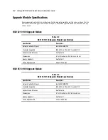
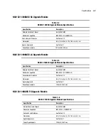
Page 27: ...Module Specifications Specification Description Network Controller Chipset Intel 82542 MAC Standards Supported IEEE 802 3z 1000BASE LX Connector and Distances See Table C 13 Dimensions 6 5 x 2 5 inches L x W 16 5 cm x 6 4 cm Agency Approvals See Table C 1 Power Requirements 1025 mA 5V max NC3133 100BASE FX Upgrade Module Table C 6 NC3133 100FX Upgrade Module Specifications Specification Descriptio...

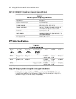
Page 28: ...equirements 2879 mA 5V maximum UTP Cable Specifications Table C 8 UTP Cable Specifications Adapter or Module Connection Speed 10 Mb s Connection Speed 100 Mb s Connection Speed 1000 Mb s Gigabit over Copper Wire EIA TIA Distance NC3134 Category 3 4 or 5 Category 5 22 26 AWG 100Ω 1 MHz 568a or 568b 100 meters NC3135 Category 3 4 or 5 Category 5 22 26 AWG 100Ω 1 MHz 568a or 568b 100 meters NC7132 Ca...

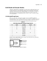
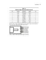
Page 29: ...traight Through Pinouts If the crossover function is implemented internally the port is labeled MDI X Medium Dependent Interface Crossover When an MDI X port is connected to an MDI port the twisted pair media should be wired straight through using the physical pinouts indicated in Table C 9 Table C 9 10 100 Pinouts Using Internal Straight Through Crossover Pin Function Color Match Function Pin 1 T...

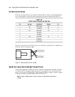
Page 30: ... Brown White Figure C 2 shows the correct 10 100 wiring to use when the crossover function is implemented externally in the twisted pair cabling Figure C 2 External crossover for RJ 45 connector Gigabit over Copper Internal Straight Through Pinouts Unlike some connections in which the crossover function is implemented internally at the hub or switch the NC7132 upgrade module provides its own autom...

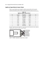
Page 31: ...DB White Green BI_DB 3 4 BI_DC Blue White BI_DC 4 5 BI_DC White Blue BI_DC 5 6 BI_DB Green White BI_DB 6 7 BI_DD White Brown BI_DD 7 8 BI_DD Brown White BI_DD 8 Figure C 3 shows straight through Gigabit over copper connector wiring to be used when the crossover function is implemented within the hub or switch Figure C 3 Gigabit over copper straight through wiring for RJ 45 connector ...

Page 32: ...er Copper Crossover Pinouts Pin Function Color Match Function Pin 1 BI_DA White Orange BI_DB 3 2 BI_DA Orange White BI_DB 6 3 BI_DB White Green BI_DA 1 4 BI_DC Blue White BI_DD 7 5 BI_DC White Blue BI_DD 8 6 BI_DB Green White BI_DA 2 7 BI_DD White Brown BI_DC 4 8 BI_DD Brown White BI_DC 5 Figure C 4 shows the correct Gigabit over copper wiring to be used when the crossover function is implemented ...

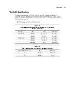
Page 33: ...dules NOTE All fiber upgrade modules use SC type connectors Table C 13 Fiber Cable Maximum Distances for 1000BASE SX 1000BASE LX NC6132 and NC6133 Fiber Type Mode Size Max Distance 1000BASE SX Multimode 62 5 125 µm 220 meters Multimode 50 125 µm 550 meters 1000BASE LX Multimode 62 5 125 µm 550 meters Multimode 50 125 µm 550 meters Single mode 10µm 5000 meters Table C 14 Fiber Cable Maximum Distanc...

Reviews: