3–18
SAN Switch Integrated/32 and Integrated/64 Installation and Hardware Guide
3–18
SAN Switch Integrated/32 and Integrated/64 Installation and Hardware Guide
Connecting the Fibre Channel Cables
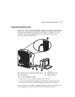
All cables connect at the front of the SAN Integrated Switch. Recommended cabling
supports a transfer rate of 1.0625 gigabytes per second (GB/s).
The SAN Integrated Switch product includes fiber-optic cables for the ISL ports.
Fiber-optic cables for the user ports are not included.
Standard fiber-optic cables can be used for the user ports. Connections can be made to the
GBICs inserted in the user ports using standard dual SC plug connectors, as shown in
Figure 3–7. The fiber-optic connectors are keyed and must be inserted into the GBIC
module connector in proper alignment.
CAUTION:
The fiber-optic cables are fragile and should not be bent to a radius of less
than 0.5 inches. Do not force the fiber-optic plug into the GBIC module as this may
damage the connector, the GBIC module, or both. Verify that the fiber-optic connector
is clean, free of dust or debris, and correctly aligned before inserting the connector
into the GBIC module.
Figure 3–7: Dual SC fiber-optic plug keyed connector
See Table 3–6 for a list of user ports in the IS/32 and IS/64 models. Refer to Figure 4–5
and Figure 4–6 to see the cable diagram for your respective model.
Table 3–6: User Ports on the SAN Integrated Switch
Switch #
IS/32
IS/64
Switch 1
None
Ports 0–7
Switch 2
Ports 0–7
Ports 0–11
Switch 3
Ports 0–7
Ports 0–11
Switch 4
Ports 0–7
Ports 0–11
Switch 5
Ports 0–7
Ports 0–11
Switch 6
None
Ports 0–7
SHR-2213A

