PM1323
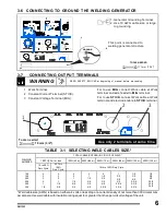
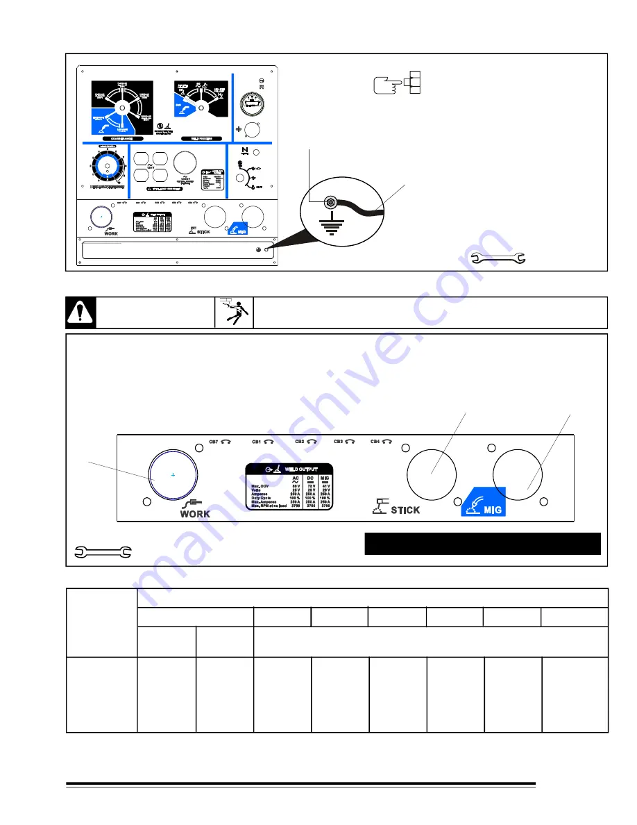
3-6 CONNECTING TO GROUND THE WELDING GENERATOR
11.1mm (7/16")
1. Generator Grounding Terminal.
TOOLS NEEDED
For to use
MIG
, connect W ork cable at W ork
terminal and wire feeder to
MIG
terminal.
For to use
STICK
, connect W ork cable at W ork
terminal and electrode cable to
STICK
terminal.
1
Work Terminal.
2
Constant Current Terminal (STICK).
3
Constant Voltage Terminal (MIG).
Use only 2 terminals at same time.
19 mm (3/4")
Tools needed
3-7 CONNECTING OUTPUT TERMINALS
WARNING
READ SAFETY BLOCKS at beginning of manual before proceeding.
100
150
200
250
300
350
4
3
3
2
1
1/0
4
3
2
1
1/0
2/0
4
2
1
1/0
2/0
3/0
3
1
1/0
2/0
3/0
4/0
2
1/0
2/0
3/0
4/0
2-2/0
1
2/0
3/0
4/0
2-2/0
2-3/0
1/0
3/0
4/0
2-2/0
2-3/0
2-3/0
1/0
3/0
4/0
2-2/0
2-3/0
2-4/0
* Weld cable size (AWG) is based on either a 4 volts or less drop or a current density of not more than 300 circular mils
per ampere. Use weld cable with insulation rating equal to or greater than the open-circuit voltage of the unit.
TABLE 3-1 SELECTING WELD CABLES SIZE.*
WELDING
AMPERES
10 to 60%
Duty Cycle.
60 Thru
100%
Duty Cycle.
100 Ft (30 m) or less
150Ft (45 m)
200Ft (60 m)
250Ft (75 m)
300Ft (90 m)
400Ft (120 m)
350Ft (105 m)
10 thru 100% Duty Cycle
TOTAL CABLE (COPPER) IN CIRCUIT OF WELD *
2. Use 10 AW G cable size or large,
to grounding
This point is connected to
welding generator structure.
1
2
3
/
F-0351
REV. A
F-0352
REV. A
GROUND
1
2
6


