R
7
SECTION - 4 OPERATION
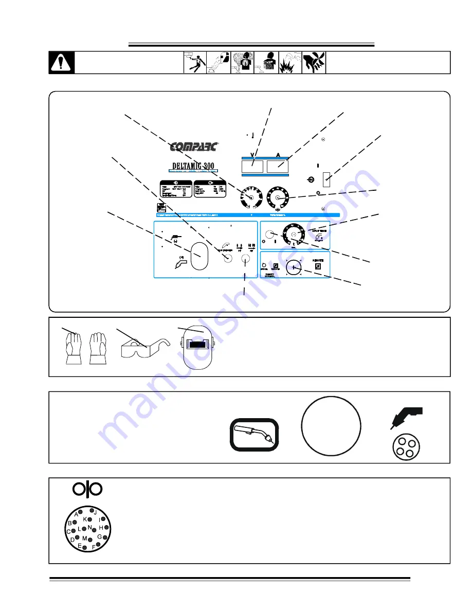
4-1 LOCATION OF CONTROLS IN WELDING POWER SOURCE.
CAUTION
SEE SAFETY SIGNALS AT THE
BEGINING THIS MANUAL
REMOTE 14
RECEPTACLE
AMMETER
WIRE SPEED
CONTROL
GUN
TRIGGER
TORCH
CONNECTOR
MAIN
SWITCH
SPOT
SWITCH
SPOT TIME
CONTROL
VOLTMETER
ADJUSTMENT
VOLTAGE
2T/4T SELECTOR
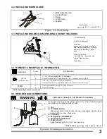
FIGURE 4-2 SAFETY EQUIPMENT
3
2
1
1- Insulating Gloves.
2- Safety Glasses With Side Shields.
3- Welding Helmet.
Wear dry insulating gloves, safety glasses with side shields, and a welding
helmet with a correct shade of filter (see ANSI Z49.1).
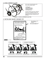
Gu n Co nnec tor.
Co nnect gun into g un
receptacle until bottom and be sure be perfectly
tighten.
FIGURE 4-3 GUN CONNECTOR.
GUN TRIGGER
GUN
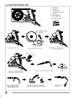
FIGURE 4-4 RECEPTACLE RC14.
RC14 RECEPTACLE.
This connector is a receptacle for a gun spool. To connect this receptacle, align
keyway, insert plug, and tighten threaded collar.
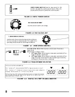
Socket Information:
SOCKET A:
24 Volts AC, 10 Amperes, 60 Hz., respect G socket (common).
SOCKET B:
Contact closure to pin A completes 24 Volts AC contactor control circuit
SOCKET G:
Circuit common for 24 and 120 VAC circuit.
SOCKET I:
120 VAC respect socket G.
SOCKET J:
Contact closure to pin I completes 120 VAC contactor control circuit.
SOCKET K:
Common
.
REMAINING SOCKETS ARE NOT USED.

