TABLE OF CONTENTS
ARC WELDING SAFETY PRECAUTIONS ............................................................................... i
SECTION 1 -- SAFETY SIGNAL WORDS ................................................................................ 1
SECTION 2 -- SPECIFICATIONS ............................................................................................. 1
2 - 1.
Volt-Ampere Curves ..........................................................................................................................
1
2 - 2.
Duty Cycle .......................................................................................................................................
2
SECTION 3 -- INSTALLATION ................................................................................................. 2
3 - 1.
Selecting a location and moving welding power source ......................................................................
2
3 - 2.
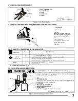
Installing work clamp ........................................................................................................................
3
3 - 3
Installing welding gun (W elding gun not included) ......................................................................
3
3 - 4.
Remote-14 receptacle information .....................................................................................................
3
3 - 5.
Shielded gas connections ................................................................................................................
3
3 - 6.
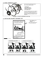
Spool wire installation .......................................................................................................................
4
3 - 7.
Setting gun polarity for wire type .......................................................................................................
4
3 - 8.
Selecting a location and connecting input power. ..............................................................................
5
3 - 9.
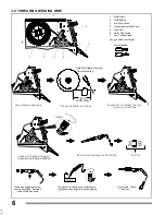
Threading welding wire... .................................................................................................................
6
SECTION 4 -- OPERATION ......................................................................................................7
4 - 1.
Location of controls in welding power source .....................................................................................
7
4 - 2.
Safety equipment .............................................................................................................................
7
4 - 3.
Gun connector .................................................................................................................................
7
4 - 4.
Receptacle RC14. ............................................................................................................................
7
4 - 5.
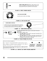
Input power switch ...........................................................................................................................
8
4 - 6.
Voltage adjust control .......................................................................................................................
8
4 - 7.
Wire speed control ...........................................................................................................................
8
4 - 8.
Trigger mode selector ......................................................................................................................
8
4 - 9.
Digital voltmeter and ammeter ..........................................................................................................
8
4 - 10. Selector of spot ................................................................................................................................
9
4 - 10. Operation sequence for GMAW, FCAW, SAW and CAC-A ................................................................
9
SECTION 5 -- MAINTENANCE AND TROUBLESHOOTING ................................................ 10
5 - 1.
Routine maintenance ......................................................................................................................
10
5 - 2.
Changing contact tip ......................................................................................................................
10
5 - 3.
Circuit breakers CB1 and CB2 .......................................................................................................
10
5 - 4.
Unit overload ..................................................................................................................................
10
5 - 5.
Troubleshootings. ...........................................................................................................................
11
SECTION 6 -- ELECTRICAL DIAGRAM................................................................................. 12
SECTION 7 -- PARTS LIST .................................................................................................... 13
7 - 1.
Main assembly ...............................................................................................................................
16
WARRANTY

