background image

ii

FLYING SPARK AND HOT METAL can
cause  injury

Chipping  and  grinding  cause  flying  metal  .  As  welds
cool,  they  can  throw  off  slag.

CYLINDERS can explode if damaged.

Shielding gas cylinders contain gas under high pressure.
If damaged, a cylinder can explode. Since gas cylinders
are  normally  part  of  the  welding  process,  be  sure  to
treat  them  carefully.

1.-  Protect compressed  gas  cylinders  from excessive  heat,  mechanical

shocks,  and  arcs.

2.-  Install  and secure  cylinders  in  an  upright  position by  chaining  them

to  a  stationary  support  or  equipment  cylinder  rack  to  prevent  falling
or  tipping.

3.-  Keep  cylinders  away  from  any  welding  or  other  electrical  circuits.

4.-  Never  allow  a  welding  electrode  to  touch  any  cylinder.
5.-  Use  only  correct  shielding  gas  cylinders,  regulators,  hoses,  and

fittings  designed  for  the  specific  application;  maintain  them  and
associated  parts  in  good  condition.

6.-  Turn  face  away  from  valve  outlet  when  opening  cylinder  valve.
7.-  Keep  protective  cap  in  place  over  valve  except  when  cylinder  is  in

use

or  connected  for  use.

8.- Read and follow instructions on compressed gas cylinders, associated

equipment,  and  CGA  publication  P-1  listed  in  Safety  Standards.

  ENGINES  can  be  hazardous.

WARNING

ENGINE EXHAUST GASES can kill.

Engines  produce  harmful  exhaust  gases.
1.-  Use  equipment  outside  in  open,  well-ventilated
      areas.

2.- If used in a closed area, vent engine exhaust outside and away from

any  building  air  intakes.

E NG I NE   F UE L   can   cau se  f ire  o r
explosion

.

Engine  fuel is  highly  flammable.

1.-  Stop  engine  before  checking  or  adding  fuel.

2.- Do  not add  fuel while smoking  or if  unit is near  any sparks  or open

flames.

3.-  Allow  engine  to  cool  before  fueling.  If  possible,  check  and  add  fuel

to  cold  engine  before  beginning  job.

4.-  Do  not  overfill  tank  -  allow    room  for  fuel  to  expand.
5.-  Do  not  spill  fuel.  If  fuel  is  spilled,  clean  up  before  starting  engine.

MOVING PARTS can cause injury.

Moving  parts,  such  as  fans,  rotors,  and  belts  can  cut
fingers  and  hands  and  catch  loose  clothing.

1.-  Keep  all  doors,  panels,  covers,  and  guards  closed
     and securely in place.
2.-  Stop  engine  before  installing  or  connecting  unit.

3.- Have only qualified people remove guards or covers for maintenance

and  troubleshooting  as  necessary.

4.-  To  prevent  accidental  stating  during  servicing,  disconnect  negative

(-)  battery  cable  from  battery.

5.- Keep hands, hair, loose clothing, and tools away from moving parts.
6.- Reinstall panels or guards and close doors when servicing is finished

and  before  starting  engine.

SPARKS can cause BATTERY GA-
SES T O EXPLODE; BATTERY ACID
can burn eyes and skin.

Batteries  contain  acid  and  generate  explosive  gases.

1.-  Always  wear  a  face  shield  when  working  on  a

battery.

2.-  Stop  engine  before  disconnecting  or  connecting  battery  cables.

3.-  Do  not  allow  tools  to  cause  sparks  when  working  on  a  battery.

4.-  Do  not  use  welder  to  charge  batteries  or  jump  start  vehicles.

5.-  Observe  correct  polarity  (+  and  -)  on  batteries.

ST EAM    AND  PRESSURIZED  HOT
COOLANT  can  burn  face,  eyes,  and
skin.

The  coolant  in  the  radiator  can  be  very  hot  and  under
pressure.

1.- Do not remove radiator cap when engine is hot. Allow engine to cool.

2.-  Wear  gloves  and  put  a  rag  over  cap    area  when  removing  cap.

3.-  Allow  pressure  to  escape  before  completely  removing  cap.

1.-  Wear  approved  face  shield  or  safety  goggles.  Side  shields

recommended.

2.-  Wear  proper  body  protection  to  protect  skin.

Summary of Contents for DELTA MIG 300

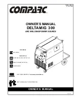
Page 1: ...0 REV 0 E 23 01 2021 PROCESSES DESCRIPTION CONSTANT VOLTAGEOUTPUT CV MIG GMAW DIRECTCURRENTOUTPUT DC THREEPHASES 3 DC CV Phases OWNER SMANUAL 302 573 T M OWNER S MANUAL VISIT OUR WEBSITE AT www comparcwelders ca GIVE THIS MANUAL TO THE OPERATOR ...

Page 2: ...n and connecting input power 5 3 9 Threading weldingwire 6 SECTION 4 OPERATION 7 4 1 Location of controlsin welding power source 7 4 2 Safetyequipment 7 4 3 Gunconnector 7 4 4 ReceptacleRC14 7 4 5 Input power switch 8 4 6 Voltage adjust control 8 4 7 Wire speed control 8 4 8 Trigger modeselector 8 4 9 Digital voltmeter andammeter 8 4 10 Selector of spot 9 4 10 Operation sequence for GMAW FCAW SAW ...

Page 3: ...tective clothing made from durable flame resistant mate rial wool and leather and foot protection 5 Use approved ear plugs or ear muffs if noise level is high FUMES AND GASES can be hazardous to your health Welding produces fumes and gases Breathing these fumes and gases can be hazardous to your health 1 Keep your head out of the fumes Do not breath the fumes 2 If inside ventilate the area and or ...

Page 4: ...le smoking or if unit is near any sparks or open flames 3 Allow engine to cool before fueling If possible check and add fuel to cold engine before beginning job 4 Do not overfill tank allow room for fuel to expand 5 Do not spill fuel If fuel is spilled clean up before starting engine MOVING PARTS can cause injury Moving parts such as fans rotors and belts can cut fingers and hands and catch loose ...

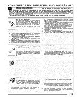
Page 5: ...ui peuvent brûler les yeux et la peau Le bruit produit par certains procédés peut endommager I ouïe Des projections de métal ou de laitier sontproduites par lepiquage le meulageou le refroidissement des soudures BRUIT 1 Utiliser des bouche oreilles ou des serre tête antibruit approuvés si le niveau de bruit est élevé RAYONNEMENTDEL ARC 2 Porter un masque à serre tête muni d un verre filtrant de nu...

Page 6: ...arrer le moteur LES PIÈCES EN MOUVEMENT peuvent causer des blessures Les pièces en mouvement comme les ventilateurs les rotors et les courroies peuvent couper les doigts et les mains et happer les vêtements amples 1 S assurer que les portes les panneaux les capots et les protecteurs sont bien fermés et bien à leur piace 2 Arrêter le moteur avant de mettre en place ou de raccorder un dispositif 3 S...

Page 7: ...r practices which must be followed to avoid seriuos personal injury or loss of life CAUTIONstatementsidentifyproceduresorpracticeswhichmustbefollowedtoavoid minor personal injury or damage to this equipment Thefollowingsafety alert symbol andsignal wordsareusedthroughout thismanual tocall attentionto andidentifydifferent levelsof hazard and special instructions 575 V 12 2 A 2 1 VOLT AMPERE CURVES ...

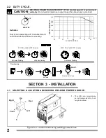
Page 8: ...that unit can weld at rated load without overheating WELDING LONGER THAN RATED DUTY CYCLE can damage unit or gun and void warranty Do not weld at rated over output longer than shown duty cycle chart CAUTION 2 2 DUTY CYCLE 6 Minutes Welding 4 Minutes Resting Continuous Welding Overheating 0 15 A or V OR Reduce Duty Cycle Minutes 60 Duty Cycle At 300 Amperes 100 Duty Cycle At 2 0 Amperes 3 DUTY CYCL...

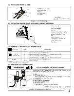
Page 9: ...er is held to running gear wall or other stationary support so cylinder can not fall and break off valve 1 CAP 2 CYLINDER VALVE Remove cap stand to side of valve and open valve slightly Gas flow blows dust and dirt from valve Close valve 3 CYLINDER 4 REGULATOR FLOWMETER 5 GAS HOSE CONNECTION 6 FLOW ADJUST Typical flow rate is 20 cfh Cubic Feet per Hour 28 5 15 8mm 1 1 8 5 8 Toolsneeded OUTPUT CONT...

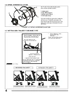
Page 10: ...POLARITY FOR WIRE TYPE 1 Polarity Changeover Label Located Near Drive Assembly Always read and follow manufac ture s recommended polarity Shown As Shipped Set For Electrode Positive DCEP For Solid Steel Or Aluminum Wires GMAW Process Wire Drive Assembly Lead To Positive Output Terminal Work Clamp Lead To Negative Output Terminal GUN POLARITY CHANGEOVER CONNECTIONS Reverse Lead Connections For Elec...

Page 11: ... input voltage Reinstall wrapper 1 in mm 0 254 for air ow 1 230 VOL 46 575 TS 0 VOLTS VOLTS 2 Do not overtighten jumper link nuts Tools Needed 3 8 in 3 8 in L1 L2 GND PE L3 GND PE Connect First 1 2 3 4 5 6 1 2 3 4 5 6 1 2 3 4 5 6 1 2 3 4 5 6 1 2 3 4 5 6 1 2 3 4 5 6 1 2 3 4 5 6 1 2 3 4 5 6 1 2 3 4 5 6 L1 L2 L3 L1 L2 L3 L1 L2 L3 Check input voltage available at site ...

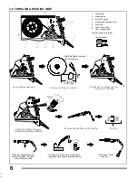
Page 12: ...eep it from unraveling Open Pressure Assembly Push Wire Thru Guides Into Gun Continue to Hold Wire Pull and Holl Wire Cut of End Tighten C T P lose and ighten ressure Assembly nd et go of ire a L W R G N C emove un ozzle and ontact tip Turn On ble s in WOOD Press gun trigger until wire comes out of gun Reinstall contact tip and nozzle Feed wire to check drive roll pressure Tighten knob enough to p...

Page 13: ... filter see ANSI Z49 1 Gun Connector Connect gun into gun receptacle until bottom and be sure be perfectly tighten FIGURE 4 3 GUN CONNECTOR GUN TRIGGER GUN FIGURE 4 4 RECEPTACLE RC14 RC14 RECEPTACLE This connector is a receptacle for a gun spool To connect this receptacle align keyway insert plug and tighten threaded collar Socket Information SOCKET A 24 Volts AC 10 Amperes 60 Hz respect G socket ...

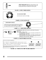
Page 14: ...e second time weld stops TRIGGER FIGURE 4 9 DIGITAL VOLTMETER AND AMMETER DIGITAL VOLTMETER AND AMMETER With contactor off Voltmeter display PRESET voltage and ammeter is turn off With contactor on Voltmeter and ammeter display actual output voltage and amperage ammeter remains off if current is zero amperes While welding the meters measure and display the output arc voltage and amperage once exti...

Page 15: ...Install and prepare Flux system Install and prepare wire feeder Set Control Turn On Flux system Beging welding Readjsut controls and begin welding Open gas valve Turn On Wire feeder and Power Source Put On safety equipment Install and prepare wire feeder Install and connect the equipment Readjsut controls and begin welding Put On safety equipment Install and prepare wire feeder Install and connect...

Page 16: ...ly FIGURE5 1 CHANGINGCONTACTTIP Turn off and disconnect the unit 1 NOZZLE 2 CONTACT TIP Cut wire remaining ofthecontacttip removeNozzle remove the contact tip and install one new Reinstall nozzle ToolsNeeded 2 1 5 2 CHANGING CONTACT TIP 5 3 CIRCUIT BREAKERS CB1 AND CB2 1 Circuit Breaker CB2 CB2 protects Remote 14 receptacle RC3 fromoverload 2 Circuit Breaker CB1 If CB1 opens wire feeding stops 3We...

Page 17: ... correct position if necessary Have Factory Authorized Service Agent check main control board Readjust front panel settings Change to correct size drive rolls Readjust drive roll pressure Replace inlet guide contact tip and or liner if necessary Check position of input jumper links Have Factory Authorized Service Agent check main control board Reset circuit breaker CB1 Turn Wire Speed control to h...

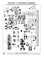
Page 18: ... Electrical Diagram DE 0160 REV 0 1 1 1 2 2 2 3 3 3 4 4 4 5 5 5 6 6 6 F1 F2 F3 F4 F5 F6 F7 1 1 1 2 2 2 3 3 575 VO LTS A C 3 4 4 4 5 5 5 6 6 6 1 1 1 2 2 2 3 3 46 0 VO LTS A C 3 4 4 4 5 5 5 6 6 6 1 1 1 2 2 2 3 3 230 VO LTS A C 3 4 4 4 5 5 5 6 6 6 ...

Page 19: ...03 COIL 1 PC2037 HEADCORE 1 15 PT3609 T1 TRANSFORMER POWER MAIN 1 PN0186 CORE 1 PB2384 COIL PRIM SEC TYPE A 1 PB2385 COIL PRIM SEC TYPE B C 1 PC2034 HEADCORE 1 16 PT2408 PANEL REAR 1 17 PR0464 BRACKET BOTTLE RETAINER 1 18 PT2426 PC5 PCB FILTER 1 19 PT2086 PC 2 CONTROL CARD CHOPPER 1 20 PT2087 PC 1 CONTROL BOARD PCB 1 21 MF02312 F1 F2 F3 FUSE 0 5A typ AGC 1 2 250V fast action 3 22 MF02311 F4 FUSE 2...

Page 20: ...FIGURE 7 1 MAIN ASSEMBLY 11 12 3 4 17 2 16 6 10 14 1 5 9 7 8 13 15 18 19 20 20 20 ...

Page 21: ... SW3 TOGGLE SWITCH 3 7 MR02583 RC 3 14 SOCKETS RECEPTACLE 1 8 MF02333 L1 LIGHT 1 9 MM04109 OPTICAL FILTER RED COLOR 1 10 PT1826 PC3 CIRCUIT CARD DIGITAL METERS 1 11 PD0098 SW1 MAIN SWITCH 1 12 MP03137 P1 POTENTIOMETER 1 Kohm 2W 1 13 MP02512 P2 POTENTIOMETER 10 Kohm 2W 1 14 PB1798 INSULATOR HOLDER 1 15 PT2454 PC 4 SIGNAL CONDITIONER CARD 1 FIGURE 7 2 PANEL FRONT W COMPONENTS 1 2 6 3 5 13 14 6 7 8 9...

Page 22: ...0924 TERMINAL PWR RED 1 5 PA1161 GUN ADAPTER 1 6 PB1769 GEARED MOTOR BASE 1 7 Mm04273 M MOTOR DRIVE GEARS 1 8 MC10192 CB 1 CIRCUITO RESET 10 AMPS 2 9 PB1770 BAFFLE CENTER 1 10 MI00665 SW3 SWITCH 1P2T 1 11 12 13 PT2463 INSULATION COVER 1 14 MR10125 R5 RESISTOR 100 OHM 50W 1 15 16 MR09545 RL 2 CIRCUIT BREAKER 120VAC 1 17 MR09883 RL 1 CIRCUIT BREAKER 24 VAC 1 FIGURE 7 3 BAFFLE CENTER W COMPONENTS ...

Page 23: ...y kind will be allowed 3 Repair time should not be more than 30 days starting from the reception of the product 4 Spare parts could be adquired in the address attached to this policy 5 The customer could ask the store where he bought the product to make efective this policy IN THE FOLLOWING CASES THIS WARRANTY IS NOT VALID a The warranty will not validin the case machines have been repaired or alt...

Page 24: ... motor drive system drive roll excluded and any other part the requires the removal of sheet metal 2 1 Year Parts Labour CG1 Dart Track Cutter excluding tracks Welding positioners turning rollers Auto darkening lens PAPR blower battery Rheostat Water Cooling Systems 3 90 Days Parts Labour Parts for Crossfire MIG guns TIG Torches Plasma Torches Spool Guns Regulators Gauges welding carts and welding...

Page 25: ...NOTES ...

Page 26: ...SERVICE CENTER FAX MAPCANADALTD 325 Healey Road Unit 1 Bolton ON L7E 5C1 Canada Phone 905 951 2788 Toll Free 800 757 4445 Fax 905 951 6256 ...

Reviews: