3
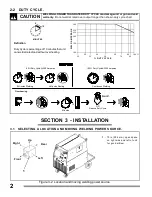
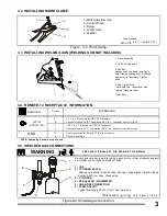
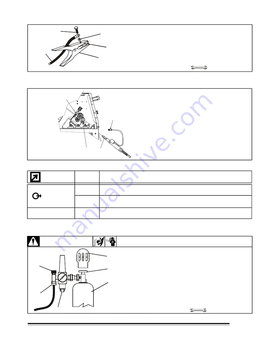
3-3 INSTALLING WELDING GUN (WELDING GUN NOT INCLUDED)
1 Drive Assembly
2 Gun Securing Knob
3 Gun End
Loosen securing knob. Insert gun
end through opening until it bottoms
against drive assembly. Tighten
knob.
4 Gun Trigger Plug
Insert plug into receptacle, and
tighten threaded collar.
Close door.
Figure 3-3 Work clamp.
3-2 INSTALLING WORK CLAMP.
9.5, 11.1 mm(3/8, 7/16")
1.- Work Cable from Unit.
2.- Contact Piece.
3.- Screw.
4.- Work Clamp.
5.- Washer.
Tools Needed
3
1
5
2
4
Figure 4-4 Shielded gas connection.
WARNING
SEE SAFETY SIGNALS AT THE BEGINING THIS MANUAL
3-5. SHIELDED GAS CONNECTIONS.
1
2
3
4
5
6
Be sure gas cylinder is held to running gear, wall, or other stationary support
so cylinder can not fall and break off valve.
1.- CAP.
2.- CYLINDER VALVE.
Remove cap, stand to side of valve, and open valve slightly. Gas flow blows
dust and dirt from valve. Close valve.
3.- CYLINDER.
4.- REGULATOR /FLOWMETER.
5.- GAS HOSE CONNECTION.
6.- FLOW ADJUST.
Typical flow rate is 20 cfh ( Cubic Feet per Hour).
28.5, 15.8mm (1-1/8",5/8")
Tools needed:
OUTPUT
(CONTACTOR)
INFORMATION
Socket
REMOTE-14
A
B
I
J
G
K
24 V a.c. Protected by CB2 (10 Amperes).
Contact closure to "A" completes 24 V a.c. contactor control circuit.
120 V a.c. Protected by CB1(10 Amperes).
Contact closure to "I" completes 120 V a.c. contactor control circuit.
Circuit common for 24 and 120 V a.c. circuits.
Chassis common.
NOTE: Remaining sockets are not used
3-4. REMOTE-14 RECEPTACLE INFORMATION.
G N D
1
2
4
3

