background image

ii

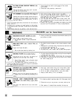
FLYING SPARK AND HOT METAL can
cause injury

Chipping  and  grinding  cause  flying  metal  .  As  welds
cool,  they  can  throw  off  slag.

CYLINDERS can explode if damaged.

Shielding gas cylinders contain gas under high pressure.
If damaged, a cylinder can explode. Since gas cylinders
are  normally  part  of  the  welding  process,  be  sure  to
treat  them  carefully.

1.-  Protect compressed  gas  cylinders  from excessive  heat,  mechanical

shocks,  and  arcs.

2.-  Install  and secure  cylinders  in  an  upright  position by  chaining  them

to  a  stationary  support  or  equipment  cylinder  rack  to  prevent  falling
or  tipping.

3.-  Keep  cylinders  away  from  any  welding  or  other  electrical  circuits.

4.-  Never  allow  a  welding  electrode  to  touch  any  cylinder.
5.-  Use  only  correct  shielding  gas  cylinders,  regulators,  hoses,  and

fittings  designed  for  the  specific  application;  maintain  them  and
associated  parts  in  good  condition.

6.-  Turn  face  away  from  valve  outlet  when  opening  cylinder  valve.
7.-  Keep  protective  cap  in  place  over  valve  except  when  cylinder  is  in

use  or  connected  for  use.

8.- Read and follow instructions on compressed gas cylinders, associated

equipment,  and  CGA  publication  P-1  listed  in  Safety  Standards.

  ENGINES  can  be  hazardous.

WARNING

ENGINE EXHAUST GASES can kill.

Engines  produce  harmful  exhaust  gases.
1.-  Use  equipment  outside  in  open,  well-ventilated
      areas.

2.- If used in a closed area, vent engine exhaust outside and away from

any  building  air  intakes.

E NG I NE   F UE L   can   cau se  f ire  o r
explosion

.

Engine  fuel is  highly  flammable.

1.-  Stop  engine  before  checking  or  adding  fuel.

2.- Do  not add  fuel while smoking  or if  unit is near  any sparks  or open

flames.

3.-  Allow  engine  to  cool  before  fueling.  If  possible,  check  and  add  fuel

to  cold  engine  before  beginning  job.

4.-  Do  not  overfill  tank  -  allow    room  for  fuel  to  expand.
5.-  Do  not  spill  fuel.  If  fuel  is  spilled,  clean  up  before  starting  engine.

MOVING PARTS can cause injury.

Moving  parts,  such  as  fans,  rotors,  and  belts  can  cut
fingers  and  hands  and  catch  loose  clothing.

1.-  Keep  all  doors,  panels,  covers,  and  guards  closed
     and securely in place.
2.-  Stop  engine  before  installing  or  connecting  unit.

3.- Have only qualified people remove guards or covers for maintenance

and  troubleshooting  as  necessary.

4.-  To  prevent  accidental  stating  during  servicing,  disconnect  negative

(-)  battery  cable  from  battery.

5.- Keep hands, hair, loose clothing, and tools away from moving parts.
6.- Reinstall panels or guards and close doors when servicing is finished

and  before  starting  engine.

SPARKS can cause BATTERY GASES
TO EXPLODE; BATTERY ACID can
burn eyes and skin.

Batteries  contain  acid  and  generate  explosive  gases.

1.-  Always  wear  a  face  shield  when  working  on  a

battery.

2.-  Stop  engine  before  disconnecting  or  connecting  battery  cables.

3.-  Do  not  allow  tools  to  cause  sparks  when  working  on  a  battery.

4.-  Do  not  use  welder  to  charge  batteries  or  jump  start  vehicles.

5.-  Observe  correct  polarity  (+  and  -)  on  batteries.

ST EAM    AND  PRESSURIZED  HOT
COOLANT  can  burn  face,  eyes,  and
skin.

The  coolant  in  the  radiator  can  be  very  hot  and  under
pressure.

1.- Do not remove radiator cap when engine is hot. Allow engine to cool.

2.-  Wear  gloves  and  put  a  rag  over  cap    area  when  removing  cap.

3.-  Allow  pressure  to  escape  before  completely  removing  cap.

1.-  Wear  approved  face  shield  or  safety  goggles.  Side  shields

recommended.

2.-  Wear  proper  body  protection  to  protect  skin.

Summary of Contents for DELTA MIG 455

Page 1: ...1327 REV 0 E 21 01 2021 PROCESSES DESCRIPTION CONSTANT VOLTAGEOUTPUT CV MIG GMAW DIRECTCURRENTOUTPUT DC THREEPHASES 3 DC CV Phase OWNER SMANUAL 302 573 T M OWNER S MANUAL GIVETHISMANUALTOTHEOPERATOR V...

Page 2: ...7 Remote14 andRemote ON OFF receptacles 6 3 8 Weldoutput terminals 7 3 9 Input powerconnections 7 SECTION 4 OPERATION 8 4 1 Location of controlsin welding power source 8 4 2 Power switch 8 4 3 Output...

Page 3: ...e clothing made from durable flame resistant mate rial wool and leather and foot protection 5 Use approved ear plugs or ear muffs if noise level is high FUMES AND GASES can be hazardous to your health...

Page 4: ...e smoking or if unit is near any sparks or open flames 3 Allow engine to cool before fueling If possible check and add fuel to cold engine before beginning job 4 Do not overfill tank allow room for fu...

Page 5: ...DTH 571 mm HEIGHT 838 mm 48 VDC WARNING CAUTION IMPORTANT Statements identify special instructions necessary for the most efficient operation of thisequipment WARNING statements identify procedures or...

Page 6: ...voltageandamperageoutputcapabilitiesof theweldingpower source Curves of other settingsfall between the curvesshown 2 2 DUTY CYCLE EXCEEDINGDUTYCYCLECANDAMAGEUNITORGUNTORCHANDVOIDWARRANTY CAUTION 100 D...

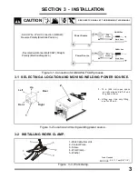
Page 7: ...STALLING WORK CLAMP Power Source 14 Pins Wire Feeder GMAW Gun Work Piece Power Source 14 Pins Wire Feeder GMAW Gun Work Piece Solid Wire Weld Connection GMAW ReversePolarity ElectrodePositive Fluxcore...

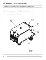
Page 8: ...over 2 and side deckl 3 as shown in figure 2 Place the support on the cover 1 and beside deck 2 as shown in figure 3 Ensure the support 1 with screws 1 4 x 1 4 Tools needed 3 8 To place the support fo...

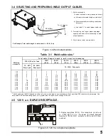
Page 9: ...3 0 2 3 0 2 4 0 3 3 0 3 4 0 3 4 0 1 0 3 0 4 0 2 2 0 2 3 0 2 3 0 2 4 0 3 3 0 3 4 0 3 4 0 4 4 0 1 0 3 0 4 0 2 2 0 2 3 0 2 4 0 2 4 0 3 3 0 3 4 0 4 4 0 4 4 0 10 60 Duty cycle 10 100 Duty cycle Welding amp...

Page 10: ...7 REMOTE 14 AND REMOTE ON OFF RECEPTACLES 1 Remote 14 receptacle RC8 See table 3 2 2 Keyway 3 Plug connector 14 4 Collar 5 Remote ON OFF receptacle See table 3 3 To connect this receptacle align keywa...

Page 11: ...fuse Figure3 9 Inputpowerconnections 3 9 INPUT POWER CONNECTIONS 3 2 4 1 Tools Needed ELECTRICK SHOCK can kill WARNING ELECTRICK SHOCK can kill WARNING Input voltage Rated input current Fuse or circui...

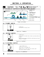
Page 12: ...and turn off the power source ON OFF POWER ON REMOTE OUTPUT OUTPUT switch PANEL position for front panel control of output weld output terminals are energized REMOTE position for remote control of ou...

Page 13: ...prox 4 sec subsequently shown PRESET value 9 VOLTAGE ADJUSTMENT VOLTAGE ADJUSTMENT control To increase arc voltage output turn control clockwise Voltmeter value changes as control is turned While weld...

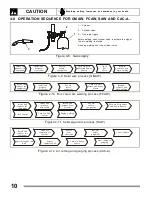
Page 14: ...igure 4 11 Submerged arc process SAW Readjsut controls and begin welding Open gas valve Turn On Wire feeder and Power Source Put On safety equipment Install and prepare wire feeder Install and connect...

Page 15: ...l continue to operate when the machine has a temperature to operate safely restart output and the message ESP ErE disappears 4 On the one overheating or failure in the cooling system the machine will...

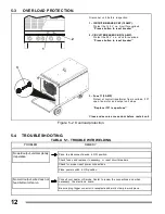
Page 16: ...sconnet unit before inspection 1 CIRCUIT BREAKER CB1 10 AMP Protect the 120 V c a cicuit for overload Presss button to reset breaker 2 CIRCUIT BREAKER CB2 10 AMP Protect the 24 V c a cicuit for overlo...

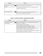
Page 17: ...rce Consult your dealer or Service Center to review mechanism connections and when necessary the electronic board in wire feeder TABLE 5 2 TROUBLE WITH MIG GUN AND WIRE FEEDER Wire feed but stops duri...

Page 18: ...455 1 1 1 1 1 1 1 1 1 2 2 2 2 2 2 2 2 2 3 3 3 3 3 3 57 5 V O LT S A C 46 0 V O LT S A C 23 0 V O LT S A C 3 3 3 4 4 4 4 4 4 4 4 4 5 5 5 5 5 5 5 5 5 6 6 6 6 6 6 6 6 6 1 1 1 2 2 2 3 3 3 4 4 4 5 5 5 6 6...

Page 19: ...forMIG gun Panel left side Panel right side ControlPCB Digital meter PCB Panel rear ASSEMBLY Blade 16 VA 407 Motorpower1 6PSC481646 0883 Resistor ww 20 ohm 10 300W Support rubberNo 4 Resistor ww 200...

Page 20: ...16 Figure 7 1 Main assembly 6 3 2 18 17 5 16 1 4 11 23 7 19 20 15 14 12 9 10 25 8 26 24 27...

Page 21: ...PT2750 MT08386 PB1963 PB1961 PT2752 PT2758 MA02821 1 2 3 4 5 6 7 8 9 10 11 12 13 3 14 15 16 17 5 18 Heatsinkintermediatelarge Heatsink intermediate small Heatsink for AC Heatsink connection left Heats...

Page 22: ...motor drive system drive roll excluded and any other part the requires the removal of sheet metal 2 1 Year Parts Labour CG1 Dart Track Cutter excluding tracks Welding positioners turning rollers Auto...

Page 23: ...NOTES...

Page 24: ...SERVICE CENTER FAX MAP CANADA LTD 325 Healey Road Unit 1 Bolton ON L7E 5C1 Canada Phone 905 951 2788 Toll Free 800 757 4445 Fax 905 951 6256...

Reviews: