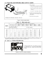
3-4 SELECTING AND PREPARING WELD OUTPUT CABLES.
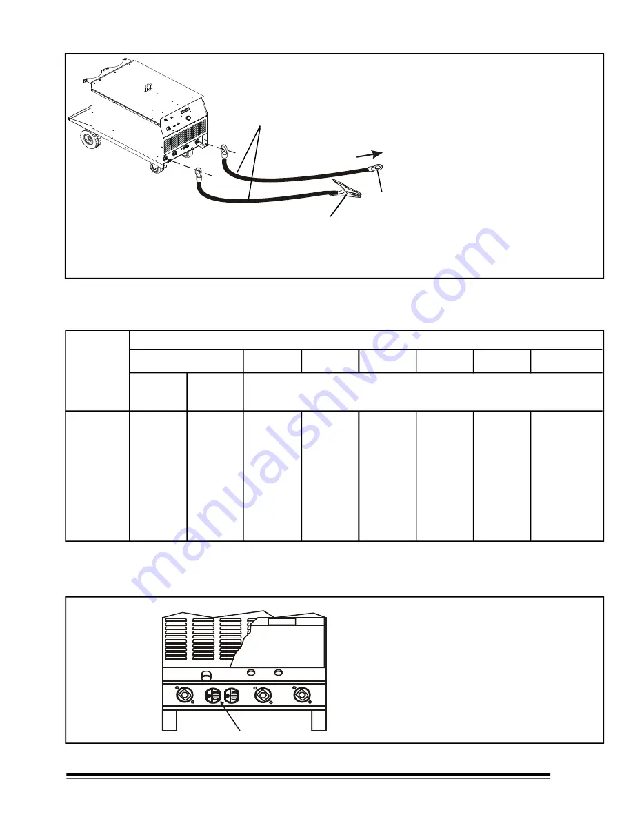
1.- Weld circuit cable.
To select weld cable size, proceed as follows
:
a)- Calculate total cable length in weld circuit
b)- Determine maximum welding current and
duty cycle.
c)- Use table 3-1 to select proper cable size.
2.- Terminal lug. Use lugs of proper amperage
capacity and hole size for connecting to weld
output terminals.
3.- Work clamp. Instal on work cable.
Figure 3-4 Weld output cables
5
60 -100%
Duty cycle
100
150
200
250
300
350
400
500
600
700
800
4
3
3
2
1
1/0
1/0
2/0
3/0
4/0
4/0
4
3
2
1
1/0
2/0
2/0
3/0
4/0
2-2/0
2-2/0
4
2
1
1/0
2/0
3/0
3/0
4/0
2-2/0
2-3/0
2-3/0
3
1
1/0
2/0
3/0
4/0
4/0
2-2/0
2-3/0
2-4/0
2-4/0
2
1/0
2/0
3/0
4/0
2-2/0
2-2/0
2-3/0
2-4/0
3-3/0
3-4/0
1
2/0
3/0
4/0
2-2/0
2-3/0
2-3/0
2-4/0
3-3/0
3-4/0
3-4/0
1/0
3/0
4/0
2-2/0
2-3/0
2-3/0
2-4/0
3-3/0
3-4/0
3-4/0
4-4/0
1/0
3/0
4/0
2-2/0
2-3/0
2-4/0
2-4/0
3-3/0
3-4/0
4-4/0
4-4/0
10 - 60%
Duty cycle
10 - 100% Duty cycle.
Welding
a mp e r e s
150 ft
(45 m)
200 ft
(60 m)
250 ft
(75 m)
300 ft
(90 m)
350 ft
(105 m)
400 ft
(120 m)
100 ft (30 m) or less
* Weld cable size (AWG) is based on either a 4 volts or less drop or a current density of not more than 300 circular mils per ampere. Use
weld cable with insulation rating equal to or greater than the open-circuit voltage of the unit.
Table 3-1 Weld cable size.*
Total cable (Copper) length in weld circuit not exceeding
1
.-Duplex receptacle (RC2), this receptacle provide up
to (120V @10 A) a.c., the power is shared between
Remote-14 (RC8), CB1 protects to RC2 and RC8 from
overload.
Figure 3-5. 120 V a.c. duplex receptacle.
3-5 120 V a.c. DUPLEX RECEPTACLE.
1
2
3
10 ft (3m)
10 ft (3m)
For Example, Total cable length in weld circuit = 20 ft (6 m)
1
To wire feeder.

