‘elevons’ -
not
as separate elevators and ailerons. You should fit 2 servos in each wing, one for
each surface, and this does give some extra safety in case one servo should fail in flight. We are
aware that some customers joint the 2 surfaces in each wing together, and use a single servo
for each wing, but we strongly recommend that you follow our instructions and use 2 servos and
separate surfaces as shown here.
Servo Choice:
The new Rookie is really quite fast and has large elevon surfaces, and there-
fore we strongly recommend that you use high quality servos of at least 8kg torque on each con-
trol surface. If fitting a powerful turbine please use hi-torque digital servos like the JR8411’s
shown here. It is also wise to fit heavy-duty servo output arms, as shown.
To get equal throws on each surface all 4 horns must be
glued in with the same angle and with the holes for the cle-
vises the same distance from the wing. Therefore, just glue
in
one
horn to start with. Use a slow epoxy and micro-bal-
loons mixture. Protect the wing surface with plastic tape and
some clear wax, and cut thru’ with a sharp knife to expose
the slots. This makes the clean-up easy after the glue is dry.
When dry make a template of the 1st horn with some scrap
ply wood and an old 1.6mm (1/16”) drill or short piece of
wire, carefully marking the hinge slot line on the template,
and use this to glue in the other 3 horns (see photos P23, 24
and 25)
Each wing has servo hatches in the bottom for a pair of ser-
vos, one to control the outer surface and one for the inner.
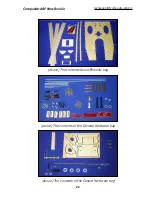
Assemble the milled plywood servo mounts as shown, and
screw your servos into position using the 2.9Ø x 13mm
sheetmetal screws provided in the kit -
not
the standard
ones that come with new servos. Note that 2 of the servo
mounts have tapered top rails, which are for the
outer
ser-
vos to make sure that they clear the wing top surface, the
narrowest part towards the trailing edge of the wings. The 2
with parallel top rails are for the inner servos. We advise that
you mark each servo hatch at this stage. (eg: ‘right inner’, ‘right outer’, etc).
Trial fit the servos into the wing with the servo hatches and adjust the position so that the servo
arms line up exactly with the phenolic control horns. Rough up the inner surface of the hatches
carefully with 80 grit, and glue the servo mounts on with a drop of CA. Check position, and when
satisfied glue them on securely with a good fillet of epoxy. These are important joints so make
sure to prepare the surfaces well before gluing together.
Make up the linkages using the M3 all-thread rod, steel clevises and lock nuts provided.
Remember to Loctite the clevise on one end (see photos). Adjust the milled slots in the wings
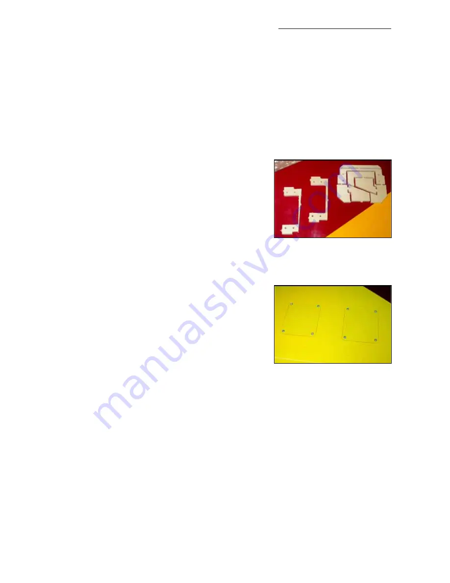
to clear the linkages at full throws. The hatches are finally secured to the bottom wing surface
with 4 each of the 2.9Ø x 10mm sheetmetal screws provided.
The servos in each wing are connected together using a ‘Y’ lead, and a standard ‘Delta wing’ mix
in used in the transmitter to give you pitch and roll control.
Please take careful note of the control surface throws recommended for the new Rookie at the
end of this manual, at least for the first flights, as they are reduced from the original Rookie due
to the powerful pitching effect of the canards.
Composite-ARF New Rookie
techsupport@composite-arf.com
12
(above) Shows the tapered and
parallel top servo mounting rails.
(below) Hatch covers secured
with 2.9 Ø x 10mm screws.


