background image

Compress iUV600s Series User Guide 

Initial Setup & Basic Operations 

32 


Avoid the following temperature and humidity conditions. Otherwise, printed images may appear 
differently from what you expect and machine operation may be erratic or incorrect.  


Places where sudden changes in temperature or humidity are expected, even if the condition is 
within the range specified within this document. 


Places where direct sunlight or excessive lighting conditions are expected 


Places where air conditioners blow directly. 

Impression Technology strongly recommends that the printer should be installed where air 
conditioning airflow, humidity and temperature can be adjusted easily. 


2.3.2


Required Space 

Install the printer on a flat surface that meets the following conditions: 


The load bearing surface will fully support the full weight of the printer (and/or stand) plus 
100%. 


The load bearing surface has an angular difference from level by no more than 2 degrees. 


The load bearing surface is textured and firm enough to be considered a non-slip, hard 
surface. 


The load bearing surface will fully support lateral forces in all directions in excess of 100kg. 


For printer options  

 Section 6.3 Options/Supplies List  p.159


Do not use the Compress iUV600s series on unstable surfaces. 


NOTE 

NOTE 

Summary of Contents for IUV600S SERIES

Page 1: ...T ANY OTHER LIABILITY IN CONNECTION WITH THIS CONTENT IN NO EVENT SHALL THE WRITER BE LIABLE TO THE READER OF THE CONTENT OF THIS DOCUMENT OR ANY SUBSEQUENT USER INCLUDING THE ULTIMATE END USER IN CON...

Page 2: ...Compress iUV600s Series User Guide 2 This page has been intentionally left blank...

Page 3: ...marks Mentioned in this Manual COMPRESS iUV600s WIMS AOD ACCULOK AND BMS are registered trademarks or product names of IMPRESSION TECHNOLOGY Centronics and BiCentronics are registered trademarks or pr...

Page 4: ...F ANY KIND THE CREATOR OF THIS DOCUMENT HEREINAFTER REFERRED TO AS THE WRITER HEREBY DISCLAIMS ALL WARRANTIES EXPRESSED IMPLIED OR OTHERWISE INCLUDING WARRANTIES OF MERCHANTABILITY FITNESS FOR A PARTI...

Page 5: ...d fully understand the contents and directions in this manual B Manual Configuration Section Contents 1 Safety Instructions Explains types of warnings cautions and warnings labeled on the printer for...

Page 6: ...Guide iv C Document Change History This version of the document replaces and obsoletes all previous versions The following table describes the most recent changes Revision Date Summary of Changes 15th...

Page 7: ...serious bodily injury or catastrophic damage to your equipment Must be observed to avoid slight or moderate bodily injury or damage to your equipment Contains important information and useful tips on...

Page 8: ......

Page 9: ...e Warning Labels 11 1 4 2 Locations of Warning Labels 12 2 Product Overview 13 2 1 Introduction Error Bookmark not defined 2 2 Features 13 2 2 1 High Resolution Image Quality 13 2 2 2 Ink Supply Syste...

Page 10: ...uirements 31 3 5 Basic Operations 32 3 5 1 Switching the Printer ON 32 3 5 2 Switching the Printer OFF 34 3 5 3 Connecting the Printer to the PC 35 3 5 4 Confirming Default Settings 37 3 5 5 Performin...

Page 11: ...djust Printing Bed Height Move Platen to the Top of Page position 91 4 5 Print Your Image 91 4 6 Post Printing 92 4 7 Cancelling a Print Job 93 4 7 1 Introduction 93 4 7 2 Cancelling the Print Job 93...

Page 12: ...Strip 110 5 5 4 Clean the CR Guide X Rail 113 5 5 5 Clean the CR Drive Belt Roller and Pulley 114 5 6 General Care 114 5 6 1 Environment 114 5 6 2 Clean your Compress iUV600s 115 5 6 3 Avoid White In...

Page 13: ...6 3 4 Problems with Curing Washing Error Bookmark not defined 6 3 5 Other Problems 153 7 Appendix 154 7 1 Product Specifications 155 7 1 1 Main Unit Specifications 155 7 1 2 Print Operation Specificat...

Page 14: ...Compress iUV600s Series User Guide 6...

Page 15: ...Cautions and Notes Safety terms in this manual and the contents of warning labels attached to the printer are categorized into the following three types depending on the degree of risk or the scale o...

Page 16: ...not use the power cable if it is damaged in any way Doing so may result in electrical shock or fire Do not insert or drop metal or objects which are easily combustible through the openings such as th...

Page 17: ...n a horizontal position even whilst it is being lifted or moved Do not leave the printer on a slanted surface Do not leave the printer upside down Doing so may cause ink leakage and or trouble that ca...

Page 18: ...eath When connecting or removing an FFC type cable on a main board assembly connector make sure to connect or remove the cable perpendicular to the connector Connecting or removing at a slant may dama...

Page 19: ...ning labels Make sure that all warning labels can be recognized If text or illustrations cannot be seen clearly clean or replace the label When cleaning warning labels use a cloth with water or neutra...

Page 20: ...ocations of warning labels are shown below Ref Warning Label Type A Using this area as a lift point will cause damage to the printer B Do not touch anything in this area unless instructed C Dangerous...

Page 21: ...nk supply system and a patented White Ink Management System WIMS utilising high performance brushless motors designed to provide trouble free accurate white ink delivery at all times 1 4 3 Operation E...

Page 22: ...rview 14 1 5 Part Names and Functions Part names and functions are explained in this section For the directions described in this document refer to the following orientation figure Left Upper Rear Fro...

Page 23: ...Front Section FIGURE 0 2 PRINTER FRONT SECTION PARTS Emergency stop LCD and keypad Bed up down buttons status light Bed Load eject buttons status light Waste ink access and cooling system access Pres...

Page 24: ...move the bed into the end of print position in which the bottom most area of the bed will be situated in the entry point of the printer Bed STATUS light GREEN indicates that the bed is loaded in to t...

Page 25: ...nector Connector to connect a network interface cable USB cable connector Connector to connect a USB cable TABLE 0 2 PRINTER REAR SECTION PARTS FUNCTION FIGURE 0 3 PRINTER REAR SECTION PARTS Media tra...

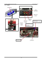
Page 26: ...uct Overview 18 1 5 3 WIMS FIGURE 0 4 WIMS PARTS Magnetic Stirrer Motor WIMS Pump WIMS mode button WIMS Status Light WIMS Rest Setting WIMS Stir Setting WIMS Filter Provision for clear Ink bottle WIMS...

Page 27: ...power is being applied to the WIMS WIMS status light GREEN indicates that WIMS has operated for a total of less than 1500 hours AMBER indicates that WIMS has operated for more than 1500 but less than...

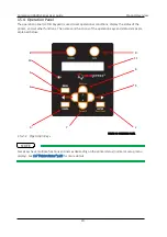
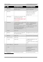
Page 28: ...status of the printer and set other functions The names and functions of the operation keys and status lamps are explained below 1 5 4 1 Operation Keys Some keys have multiple functions and names depe...

Page 29: ...During reception analysis Deletes the data that has been already received analysed and ignores 1 file of data received after that Returns to the previous menu hierarchy Changed parameter values are di...

Page 30: ...printer is analyzing received data The printer is printing data Blinking The printer is receiving data Off The printer is not receiving analyzing or printing data 3 Roll lamp Green On The printer is s...

Page 31: ...o be made using the operation panel 1 6 3 Changing Printer status 1 Normal Setup Menu Display When the printer is in normal mode press the Menu key The operation panel will shift to the setup menu dis...

Page 32: ...Compress iUV600s Series User Guide Initial Setup Basic Operations 24 2 Initial Setup Basic Operations...

Page 33: ...r 1 Position the printer 2 3 Choosing a Place for the Printer p 28 2 Remove packaging materials 2 6 1 Removal of Shipping Tape p 44 3 Load colour inks before power is applied to the printer 2 6 3 Prim...

Page 34: ...lue LED s illuminated 3 Release and move carriage away from the capping station as per picture below At this point you will hear the pump running this means that the system will be starting to prime l...

Page 35: ...lso of your commitment to your new business opportunity with the Compress iUV600s Whilst the mechanics of the printing unit of the iUV600s are similar to that of a normal inkjet printer printing on ri...

Page 36: ...get too carried away though and start accepting orders before you even have your printer Allow plenty of time to become familiar with your printer and to learn not only the basics but also the variab...

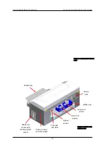
Page 37: ...uide 29 Media tray Mains inlet Ethernet and USB WIMS unit Pump and stirrer Colour ink bottles Optical sensor Waste ink access and cooling system access Pressure reset and status light FIGURE 2 3 PRINT...

Page 38: ...Compress iUV600s Series User Guide Initial Setup Basic Operations 30...

Page 39: ...or dustyareas Failureto do so mayresultin electrical shock or fire 2 3 1 Installation Environment Requirements Choose a place for printer installation following the requirements of the table below Ins...

Page 40: ...ly recommends that the printer should be installed where air conditioning airflow humidity and temperature can be adjusted easily 2 3 2 Required Space Install the printer on a flat surface that meets...

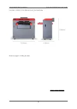
Page 41: ...Initial Setup Basic Operations Compress iUV600s Series User Guide 33 Compress iUV600s Printer dimensions are illustrated below Machine weight 148kg uncrated FIGURE 2 4 IUV600S DIMENSIONS...

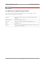
Page 42: ...nsure optimum performance of your printer and the RIP Processor Requires a PC based on Quad Core 2 2 GHz technology or higher processor Operating System Microsoft Windows XP or later Hard Disk Hard Dr...

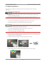
Page 43: ...e emergency stop is engaged by pressing hard on the red cap 2 Plug the supplied mains cord into the socket at the rear of the printer Pay attention to the following when handling the power cable Do no...

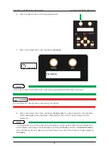
Page 44: ...After a short delay the screen will display No Waste Tank for approximately 15 seconds after which Cover Open will be displayed indicating that the printer is ready to begin normal operations 9 To br...

Page 45: ...ation panel display will be blank 2 Ensure that the emergency stop is engaged by pressing hard on the red cap 3 Unplug the power cord from the rear of the printer During normal non operational periods...

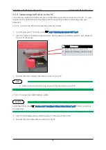
Page 46: ...Printer OFF p 34 Insert the network interface cable connector into the network interface connector port located at the rear of the printer Connect the other network interface connector to your PC Refe...

Page 47: ...supports USB 2 0 If the connection is made under the following conditions the speed may decrease to the level measure ins USB1 1 o When the USB connection is used in Windows 98 o When your PC does not...

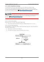
Page 48: ...not to alter the default settings of the printer If it is necessary to enter the Setup Menu for any reason follow the instructions below carefully and ensure that settings are maintained as described...

Page 49: ...al and is in ready to print status Display will read Ready to Print 2 Press the Menu key on the operation panel Menu TestPrint will be displayed on the operation panel The setup menu display will be d...

Page 50: ...itor of the operation panel is blinking it s setting can be changed Press the Forward key or Reverse key to change the setting 5 To save the changed setting press the Enter key on the operation panel...

Page 51: ...ions Compress iUV600s Series User Guide 43 6 Press the Menu key or Cancel key on the operation panel to exit from the setup The previous setup menu will be displayed 3 When the main menu is displayed...

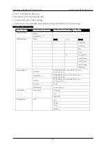
Page 52: ...tup Menu Sub Menu Item Setting Value Test Print Menu Setup NozzleCheck MediaSet Menu Media Plain Effect None Fine Fog Fine Fuzz Fog Wave PF ConfirmPrint InitialChange InitialPrint MicroChange MicroPri...

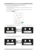
Page 53: ...3 Open the top hood of the machine in order to deactivate the LED lamps cleaning cycles with LED lamps active are strongly discouraged 4 Press and hold the ENTER key 5 The operation panel will display...

Page 54: ...operation this is normal with all printers Executing a 2nd Head Cleaning from the operation panel within one print of the 1st Head Cleaning will trigger a longer than Normal clean Ensure that the was...

Page 55: ...ired for this procedure 1 Remove any tape from the printer top cover lid then open the top cover lid 2 Locate the shipping tape near the centre part of the carriage belt as shown 3 Carefully remove th...

Page 56: ...red carriage lock bracket located at rear of print head carriage remove the carriage lock bracket Failure to remove the carriage lock bracket before powering up the printer may result in catastrophic...

Page 57: ...ou must first prime the entire lamp cooling system The reservoir for the pump is located in the waste tank bay via the small grey door The Pump unit and reservoir are located to the right as shown bel...

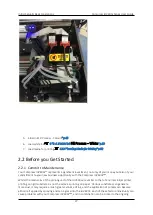
Page 58: ...ge away from the capping station as per picture below At this point you will hear the pump running this means that the system will be starting to prime look at the cooling tubes connecting to the lamp...

Page 59: ...they are empty There may be a small quantity of shipping fluid inside which will need to be poured out 2 Fill each container with UV ink to just below the curve at the top of each container as shown...

Page 60: ...the top cover of the printer to ensure LED lamp limit switch is switched off 4 No Part name 1 LED lamps indicator lights 2 Coolant pipes 3 CR board assembly cover LED lamp limit switch located behind...

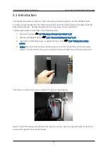
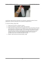
Page 61: ...ound inside the white ink bottle when first unpacking the machine 2 Unscrew the white ink container lid by holding the lid and rotating the container There will be a small quantity of shipping fluid i...

Page 62: ...7 Push the media tray all the way to the back of the machine 8 Press the load button and load LED will illuminate green 9 Screen will display RAM CAPACITY press cancel 10 Screen will display CHECK TES...

Page 63: ...t your product representative for more information on these optional components As you are now ready to print your first test print or nozzle print please review the steps undertaken to get to this po...

Page 64: ...dia tray If it is necessary to move the media tray manually it must be done at a speed of no greater than 60mm second 2 inches second 1 Push the platen tray forwards so that about half of the platen i...

Page 65: ...ll emit a series of beeps and after a short delay the platen will move into the printer Do not impede the platen tray during operation as this may damage the printer 4 When the printer has loaded the...

Page 66: ...nt is Menu Enter Forward Enter The printer will print a pattern which should resemble the picture below Each horizontal line represents the output from each of the nozzles There will be an identical p...

Page 67: ...Initial Setup Basic Operations Compress iUV600s Series User Guide 59 deactivated The nozzle check print will not cure in this case and can be cleaned using Isopropyl or denatured alcohol...

Page 68: ...ely to be physical damage to the print head face possibly by the print head face striking the platen surface or the media which is preventing the affected nozzles from ejecting any ink If any of the a...

Page 69: ...test print pattern from which it will be necessary to identify the difference between the position of the dots printed in the CW direction and those printed in the CCW direction That is the test patt...

Page 70: ...sing the Self Diagnosis Menu To access the Adjustment menu select the self diagnosis menu on the operation panel and simultaneously put the bed operation into diagnostic mode The self diagnosis menu i...

Page 71: ...ty If one of the bed buttons load eject etc is pressed at this stage it is likely that the screen display will progress to RAM Capacity 256Mb Use the following operation flow shown here to return the...

Page 72: ...lect the Check Adjustment menu option the Print Head will release from the Capping Station and make small movements some noise for 15 20 seconds or so before settling back into the Capping Station Thi...

Page 73: ...ss Next key or Back key in the operation panel to scroll through the menu Then press Enter key to confirm the menu option displayed The button presses required to select the first Bi Directional optio...

Page 74: ...the UP button the platen will begin to rise until the internal safety beam detects that the platen height is correct The platen LED will go red and the platen will stop moving release the UP button an...

Page 75: ...printer until the front of the Media Tray clears the Media Switch which is located on the left hand side of the printer bed beneath the printer carriage area Then from the front of the printer pull th...

Page 76: ...attern will be printed 13 The platen will not eject after the test print has completed so manually pull the platen out to the front of the printer far enough that you can examine the test print patter...

Page 77: ...own for each printer will differ 15 Press ENTERto set the new offset value To shift the centre vertical bar in a left direction as per Figure 3 Desired Alignment above decrease the offset value In the...

Page 78: ...hat new media is loaded firstly press the EJECT button the Load Eject LED should show red Manually pull the platen to the rear of the printer so that the rear media sensor interrupter is in line with...

Page 79: ...e installing the printer driver for network connection then it is necessary that you set the network IP address in the printer before you install the printer driver Be sure to set the IP address after...

Page 80: ...Address comprises 4 segments use the Enter key to move between segments 2 6 9 2 Installing the Printer Driver for network connection 1 The printer should be connected to the network before installing...

Page 81: ...matically start browse the CD to the driver folder and then to the appropriate language folder and execute Setup exe from the CD 6 If necessary allow the necessary actions from any User Account Contro...

Page 82: ...splay will move to the next screen 9 The license agreement for the driver software will display a If you agree to the written contents click Agree The display will move to the next screen b If you do...

Page 83: ...river has previously been installed proceed to step 10 11 Make settings in the dialog box for the following items and then click OK a Port name Enter an arbitrary name b IP Address Enter the IP addres...

Page 84: ...ts that were installed in the past are displayed on the output port list a To use an output port that was installed in the past select it from the output port list and then click OK Proceed to step 13...

Page 85: ...eries User Guide 77 Select MUTOH Network Port and then click New Port Proceed to step 11 13 Set the printer name and then click Next If you do not need to change the printer name use the default name...

Page 86: ...click Next The driver installation will begin 15 During the driver installation a Windows security warning may be displayed If necessary click Install 16 Once the printer driver has been installed the...

Page 87: ...efer to Section 2 6 9 4 If you have connected using the USB cable before installing the driver p 82 2 Turn on your PC 3 Ensure that your PC boots up correctly then insert the printer driver CD into th...

Page 88: ...ter driver installation will be cancelled The display will move to the next screen Click the installation of a driver check box and click Next The display will move to the next screen 6 The license ag...

Page 89: ...ress iUV600s Series User Guide 81 d If you do not agree to the written contents click Cancel The installation of the driver will be cancelled The display will move to the next screen 7 Click USB The d...

Page 90: ...ontent and if there is no problem click Next 9 If the Windows security warning is displayed during the installation click Install 10 At this stage the installer is waiting for the printer to be connec...

Page 91: ...inter has not been fully prepared click Connect later The driver installation will begin Once the driver has been installed to Windows the USB connection dialog will automatically close 11 If you are...

Page 92: ...ial Setup Basic Operations 84 12 Click End This completes the printer driver installation If you click menu the first screen of the installer is displayed If the printer was not connected during the i...

Page 93: ...B connection p 76 Select Connect it later in step 10 of Section 2 6 9 3 Installing the Printer Driver for USB connection p 76 2 Connect the USB cable 3 Turn the printer ON 4 Devices and Printers from...

Page 94: ...Compress iUV600s Series User Guide Initial Setup Basic Operations 86 6 Select Apply this correction 7 Check that the problem is solved and then finish troubleshooting...

Page 95: ...d Printers from Control Panel on your PC 2 Select RJ 901X which is displayed as an unspecified device and click Remove device 3 Turn the printer OFF 4 Remove the USB cable 5 Follow the procedure from...

Page 96: ...Compress iUV600s Series User Guide Printing to substrates 88 3 Printing to Rigid Substrates...

Page 97: ...ial that you have a basic understanding of image or graphic types in order to understand your artwork 1 Vectors Vector graphics are made up of mathematical outlines and curves that make the shapes in...

Page 98: ...dots per inch the less jagged the image will look It will also increase the data size of the file considerably Dots per inch or DPI is the measurement of the pixel density One example of low DPI imag...

Page 99: ...other than white it is almost impossible to match the digital colour with the colour of the media In programs such as Photoshop the file data includes transparent pixels as a background colour of cho...

Page 100: ...underbase forms a special receptive surface for the UV ink to adhere to POOR PRIMER POOR PRINT QUALITY Many substrates will not require any form of preparation and can be printed and packed without ad...

Page 101: ...rops that occur when the sprayer is starting up Keep the sprayer about 12 inches 0 3 meters from the substrate and begin spraying from the top to the bottom in a left to right and then reverse right t...

Page 102: ...on to the CompressmiUV600s Checking PRINT QUALITY Print quality is an extremely important component of the printing process You can check the print quality by printing a Nozzle Check 2 6 6 Performing...

Page 103: ...the intensity turn the knobs right or left the blue LED indicators are a visual guide only After the Compress iUV600s has finished printing the Printing Bed will automatically eject the platen to the...

Page 104: ...el the print job and start again As with any inkjet printer it is sometimes difficult to stop a print job with the Compress iUV600s once you have set it in motion Firstly press the Emergency Stop butt...

Page 105: ...Care Maintenance Compress iUV600s Series User Guide 97 4 General Care Maintenance...

Page 106: ...2 Execute a Print Head Clean at the end of production Execute a Print Head Clean at the end of your daily production 2 5 5 Performing a Head Clean from the Operation Panel p 42 4 3 Run the Nozzle Che...

Page 107: ...away from the capping station Do not allow the Carriage assembly to remain out of the capping station for longer than two or three minutes Failure to do so will result in possible blockage of print no...

Page 108: ...e honeycomb flush pad by using a small hook and lifting the pad upwards being careful not to spill liquid ink from the underneath side 3 Take not of the angle of the honeycomb ensure when re inserting...

Page 109: ...d cleaning fluid 3 Clean the gutter with a swab and cleaning fluid 4 Clean the head cap lip with a swab and cleaning fluid 5 Pour a few drops of cleaning fluid into the cap 6 Execute a normal head cle...

Page 110: ...on 4 Move the carriage to the centre of the printer 5 Clean the leading and trailing edges of the carriage with a swab and cleaning solution 1 Carefully clean the metal edges of the print head with a...

Page 111: ...process Prior to execution of this procedure it is highly recommended to discuss with your product representative 1 Place a sponge from the cleaning kit onto the machine bed 2 Pour enough cleaning flu...

Page 112: ...local regulations in disposing of its contents No tools are required for this procedure Waste ink should be checked on a daily basis and disposed of in strict accordance with local ordinances and regu...

Page 113: ...derable amount of ink and should only be used in extreme situations Ensure that the Waste Ink Container has been emptied in accordance with Section 4 4 6 Emptying the waste ink container p 101 4 5 1 1...

Page 114: ...s option when a normal head cleaning operation is not sufficient Normal Performs standard Head Cleaning TABLE 4 1 ITEMS IN CLEANING MENU Executing several consecutive Longer Cleanings may trigger the...

Page 115: ...er p 101 The powerful clean ink charge options can only be accessed through a hidden menu called the Self Diagnosis menu Note that the Self Diagnosis menu contains several menu options which are inten...

Page 116: ...self diagnosis menu follow the steps below 3 If the system is in the operation mode or the self diagnosis menu mode press Power key to turn the printer off 4 While holding down Reverse key Forward ke...

Page 117: ...turn the display to Check Test When the printer bed is put into diagnostic mode as is done in preparation for the Bi Directional adjustment by pressing holding LOAD and EJECT buttons during power up i...

Page 118: ...the self diagnosis Menu and access the Cleaning Menu 3 Press Forward key or Reverse key in the operation panel to scroll through the menu Then press Enter key to confirm the menu option displayed The...

Page 119: ...o confirm select the Check Cleaning menu option the Print Head will release from the Capping Station and make small movements some noise for 15 20 seconds or so before settling back into the Capping S...

Page 120: ...Charge option but more than Long Cleaning Ink Charge Use this option to pull a larger amount of ink through the ink lines print head 4 5 2 5 Exiting the Cleaning Self Diagnosis Menu To quit the selec...

Page 121: ...There is a sensor that sits at the rear right side of the Print Head carriage which reads these vertical marks so that the Print Head knows exactly where to spray the ink You can understand that if th...

Page 122: ...or example hitting it against frames Any dirt or scratches on the CR Encoder Strip may cause a malfunction of the CR Encoder Sensor Do not pull the CR encoder strip by force CR encoder strip guide can...

Page 123: ...lean one Release the Print Head Carriage refer 4 4 1 Accessing the Capping Station p 95 and gently slide the Print Head Carriage from it s home position This will give you easier access to the other e...

Page 124: ...up with a soft dry cloth In most instances it will not be necessary to re grease CR Guide as the Carriage moves along the guide supported by roller bearings A very small amount of White Lithium based...

Page 125: ...ller is located on the far left side of the printer Use a small brush or mini vacuum cleaner to clean the teeth of the Drive Belt and the Drive Gear You may also need to use a small sharp object and o...

Page 126: ...not spray the cleaner directly onto the printer rather onto the cloth to remove dust grime build up Ensure that any ink spills on or around the ink bottles in particular are cleaned immediately If sp...

Page 127: ...or a long period of time 1 2 weeks then you should flush the system with Cleaning Fluid No tools are required for this procedure Use protective gloves to avoid stained fingers Use recommended cleaning...

Page 128: ...rotection mechanism to help remind the user to monitor empty the waste ink container If the waste ink counter is triggered during an Ink Charge it will be evidenced by the printer appearing to freeze...

Page 129: ...fully to the rear of the printer 7 Tape the platen belt together at the front with low tack tape 8 Re affix the carriage lock bracket 9 Tape the top cover closed with low tack tape 10 Tape the ink co...

Page 130: ...Compress iUV6000s Series User Guide Troubleshooting 122 5 Troubleshooting...

Page 131: ...r 5 2 Troubleshooting with Error Messages This section describes the messages displayed in normal operation and upon an error occurrence as well as how to correct the error The available messages are...

Page 132: ...will not print 7 Turn machine OFF Disconnect mains power wait 5 minutes Turn it ON again and check if the same message appears If the message appears Contact your authorized Compress Distributor or T...

Page 133: ...essage appears Contact your authorized Compress Distributor or Technician for further assistance 2 5 2 Switching the Printer OFF p 34 2 5 1 Switching the Printer ON p 32 2 Media skew error Media skew...

Page 134: ...g Ink tube life Ink tube life has almost expired 13 Turn machine OFF Disconnect mains power wait 5 minutes Turn it ON again and check if the same message appears If the message appears Contact your au...

Page 135: ...Action Reference 1 I15 1error command Onlineframe error 15 Turn machine OFF Disconnect mains power wait 5 minutes Turn it ON again and check if the same message appears If the message appears Contact...

Page 136: ...Turn machine OFF Disconnect mains power wait 5 minutes Turn it ON again Re start computer Re send print instruction check if message appears 17 Confirm USB ports on computer are functioning correctly...

Page 137: ...stopping its operation 2 Turn OFF the driving system power automatically 3 Flash all lamps in the operation panel and generate intermittent audible alarm 4 Display the applicable error message on the...

Page 138: ...ing the Printer ON p 32 3 E016 errorCPU Err 02 Commandborder exception TLB exception loador commandfetch error Abnormal conditionin command border OrTLBexception indataloador commandfetch 4 E016 error...

Page 139: ...appears Contact your authorized Compress Distributor or Technician for further assistance 2 5 2 Switching the Printer OFF p 34 2 5 1 Switching the Printer ON p 32 8 E016errorCPU Err 07 Busexception er...

Page 140: ...your authorized Compress Distributor or Technician for further assistance 2 5 2 Switching the Printer OFF p 34 2 5 1 Switching the Printer ON p 32 14 E016 errorCPU Err 13 Trap exception error Trap oc...

Page 141: ...achine OFF Disconnect mains power wait 5 minutes Turn it ON again and check if the same message appears If the message appears Contact your authorized Compress Distributor or Technician for further as...

Page 142: ...e same message appears If the message appears Contact your authorized Compress Distributor or Technician for further assistance 2 5 2 Switching the Printer OFF p 34 2 5 1 Switching the Printer ON p 32...

Page 143: ...ace CR Encoder Strip If the message appears Contact your authorized Compress Distributor or Technician for further assistance 4 5 3 Clean the CR Encoder Strip p 110 2 5 2 Switching the Printer OFF p 3...

Page 144: ...umpphase sensoror Pump 2 Turn machine OFF Disconnect mains power wait 5 minutes Turn it ON again and check if the same message appears If the message appears Contact your authorized Compress Distribut...

Page 145: ...switch at wall socket ON Connect the power cord to the wall socket for mains power Ensure mains power switch is ON 2 5 1 Switching the Printer ON p 32 Contact your authorized Compress Distributor or...

Page 146: ...ugh initial charge has started ink does not reach head 1 Are tube clamps on ink tubes properly released Release tube roller clamps from ink tubes 5 3 2 2 6 3 Primin g the cooling system Before the LED...

Page 147: ...ONS FOR INITIAL OPERATION PROBLEMS No Symptom Check Item Action Reference The Pump unit and reservoir are located to the right as shown below Reach in and lift the reservoir bottle from its location y...

Page 148: ...u will notice a green solution in the bottle this is anti freeze simply fill the bottle full with distilled water reattach the lid and then return bottle to the original location To Prime the LED lamp...

Page 149: ...apping station as per picture below At this point you will hear the pump running this means that the system will be starting to prime look at the cooling tubes connectin g to the lamps once the air ha...

Page 150: ...142 TABLE 5 8 CHECK ITEMS AND ACTIONS FOR INITIAL OPERATION PROBLEMS No Symptom Check Item Action Reference which the pump will automatic ally stop Tubes should be solid and NO air visible 12 Check th...

Page 151: ...e connectors securely tightened Is O ring properly installed Check damper and manifold assemblies If ink inflow is confirmed execute initial ink charge 4 5 1 Powerful Head Cleaning p 102 2 Does shield...

Page 152: ...Compress iUV6000s Series User Guide Troubleshooting 144 TABLE 5 8 CHECK ITEMS AND ACTIONS FOR INITIAL OPERATION PROBLEMS No Symptom Check Item Action Reference Technician for further assistance...

Page 153: ...ymptom is repeated If the symptom is repeated Contact your authorized Compress Distributor or Technician for further assistance 2 5 2 Switching the Printer OFF p 34 2 5 1 Switching the Printer ON p 32...

Page 154: ...urther assistance 2 5 2 Switching the Printer OFF p 34 2 5 1 Switching the Printer ON p 32 2 Missing dots in printing 1 Perform cleaning twice consecutively 2 5 5 Performing a Head Clean from the Oper...

Page 155: ...ap p 98 2 Is nozzle face wiped rubbed correctly Check wiper installation condition and secure it correctly 3 Does residual ink collect on print head assembly or in nozzles Clean head as follows Cleanh...

Page 156: ...Compress iUV6000s Series User Guide Troubleshooting 148 TABLE 5 9 SYMPTOMS CHECK ITEMS AND ACTIONS FOR PRINTING PROBLEMS No Symptom Check Item Action Reference Technician for further assistance...

Page 157: ...cleaning above 2 Are damper assembly ink tube damper connectors K Y M C manifold tube connectors securely tightened Is O ring properly installed Check damper and manifold assemblies 3 Does shield part...

Page 158: ...est Print 1 Is working environment appropriate Use machine under specified environment 2 3 1 Installation Environment Requirements p 28 2 Have you started printing immediately after initial charge Pri...

Page 159: ...Strip 4 5 3 Clean the CR Encoder Strip p 110 6 Is waste ink tube from ink system assembly bent blocked kinked Check for and release kink bend in waste tube from ink system assembly via waste ink compa...

Page 160: ...edges on printout Uneven lines printed with stains 1 Is working environment appropriate Use machine under specified environment 2 3 1 Installation Environment Requirements p 28 2 Is CMYK ink pressure...

Page 161: ...le face wiped rubbed correctly Check wiper installation condition and secure it correctly 8 Is waste ink tube from ink system assembly bent blocked kinked Check for and release kink bend in waste tube...

Page 162: ...n it ON again and check if symptom is repeated If the symptom is repeated Contact your authorized Compress Distributor or Technician for further assistance 2 5 2 Switching the Printer OFF p 34 2 5 1 S...

Page 163: ...ent If contamination or deposit is too heavy Replace CR Encoder Strip 4 5 3 Clean the CR Encoder Strip p 110 2 Turn machine OFF Disconnect mains power wait 5 minutes Turn it ON again and check if symp...

Page 164: ...r strip contaminated If grease or dust collect Wipe strip with a dry cloth If ink deposit presents Wipe it off with cloth dampened with neutral detergent If contamination or deposit is too heavy Repla...

Page 165: ...onnected to the computer via USB cable Check USB cable connection 2 5 3 2 Connecting USB interface cable p 35 4 Observe Check Items for Symptom 23 USB interface cannot establish communication below 5...

Page 166: ...eplace USB hub Use USB hubs compliant with USB2 0 Hi Speed standard 4 Attempt communication with using another PC on hand Replace USB cable 5 Does the same error occur even if interface cable is chang...

Page 167: ...ion Reference 24 Printing position is incorrect 1 Are settings from RIP software correct Check RIP software settings refer to RIP software user guide 2 Printer driver may be defective Update printer d...

Page 168: ...computer refer to RIP software user guide computer user guide 3 Printer driver may be defective Update printer driver 0 Installing the Printer Driver for USB connection p 76 4 Is CR encoder strip con...

Page 169: ...ithin the machine Contact your authorized Compress Distributor or Technician for further assistance 2 Abnormal noise is heard while head is moving laterally 1 Contact your authorized Compress Distribu...

Page 170: ...repeated If the symptom is repeated Contact your authorized Compress Distributor or Technician for further assistance 2 5 2 Switching the Printer OFF p 34 2 5 1 Switching the Printer ON p 32 3 Ink sp...

Page 171: ...Appendix Compress iUV600s Series User Guide 163 6 Appendix...

Page 172: ...ceramics board stock metals glass etc Maximum loadable media length 440 mm 17 5 inches 885mm 35 inches Maximum loadable media width 600mm 24 inches 600 mm 24 inches Platen bed height adjustment 285mm...

Page 173: ...ion environment 18 C 64F to 30 C 86F 20 to 80 with no condensation Printing accuracy warranty range 18 C 64F to 28 C 82 4F 40 to 60 with no condensation Rate of change 2 C hour or less 5 hour or less...

Page 174: ...Compress iUV600s Series User Guide Appendix 166 TABLE 6 3 PRINTER PHYSICAL SPECIFICATIONS...

Page 175: ...C Cable power supply 2 Data Bidirectional Data 3 Data Bidirectional Data 4 Ground Cable ground TABLE 6 5 USB INTERFACE PIN SIGNAL FUNCTION Item Specifications Interface Universal Serial Bus Specificat...

Page 176: ...ing protocol TCP IP TABLE 6 6 NETWORK INTERFACE SPECIFICATIONS 6 3 Options Supplies List 6 3 1 Options Name Model Sales units Vacuum bed with venture ejector iUV600s and 600s XL 1 box includes one uni...

Page 177: ...0i ink Compress P70i primers Compress P70i maintenance solution Compress polyester lint free cloths Compress cleaning swabs Wiper blade WIMS filter Capping station Encoder strip Solvent proof print he...

Reviews: