D
ATA
M
AXX
set the ferrule on the probe sheath.
8. Holding the probe in place, tighten the compression nut down tight.
Make certain that the
thermocouple probe is in its proper position prior to tightening the compression nut.
9. Loosen the nut to the point that the probe will turn and, if room permits, align the transition spring
and the lead wire at a 90 degree angle from the exhaust pipe. This will position the sender tip
correctly in the exhaust stream.
10.
Tighten the nut back down to secure the probe.
11. Route the probe’s cable to the junction box, using tie wraps along the way, but leaving sufficient
slack to easily insert the connector into the appropriate junction box jack.
Do not harness the
cable tightly, being sure to use sweeping bends and loosely guiding the cable to the junction
box.
This will allow the cable to absorb vibrations along its length
12.
The male connector on the end of the probe’s cable should properly mate with any of the
thermocouple jacks coming from the junction box, so pay attention to the labels on the junction box
lid in order to associate the correct cylinder with the correct channel. Insert the male connector into
the appropriate jack. It will only go on one way.
13.
The cable may be shortened if required. Cut the cable to the desired length (plus some
spare) and carefully cut the stainless steel overbraid back approximately 1”. Shrink tubing should
be used over the cable where it exists the connector to make for a neater installation. Make certain
that the overbraid in no way comes in contact with the wire terminals in the connector. Strip the
RED wire back approximately
½
” and connect to the minus (-) terminal in the connector. Repeat
the process for the YELLOW wire and connect to the positive (+) terminal. NOTE: Only this wire
can be utilized. Substitution of a different wire
will
affect the operation of the sensor.
REMEMBER - The RED wire must be connected to the MINUS (-) terminal and the
YELLOW wire must be connected to the POSITIVE (+) terminal.
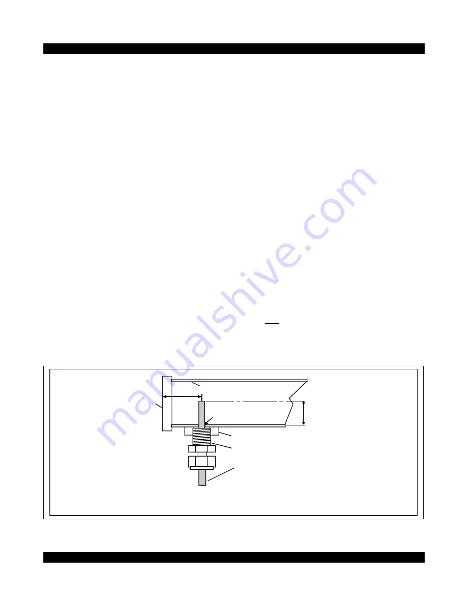
1/2 tube dia.
Header tube
flange
Weld-in header adapter
Thermocouple compression fitting
Thermocouple probe shaft
1 1/4"
Note: check for chassis clearance or
other obstructions at desired installation
location prior to drilling hole for weld-in
header adapter.
THERMOCOUPLE
INSTALLATION
DETAIL
5/16" hole in tube
(WELD-IN)
Copyright c 2008 Computech Systems Inc. 24


