background image

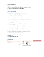
Setup


menu


To


edit


the


Setup


menu:


7


,


‘This


action


will


restore


all


user


[thermometric]


settings


to


the

Continue?’


displays.


Press


SELECT


to


confirm


or


MENU


to


exit


and


ret

screen.


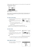
1.


Select


and


enter


the


Setup


menu


and


the


screen


opposite


appears.


2.


Use


UP


or


DOWN


to


scroll


through


the


settings


and


press


SYS


or


FAN


to


change


a


setting.


3.


Press


MENU


to


confirm.


Here’s


a


list


of


what


the


Setup


menu


settings


mean:


Unit


Changes


the


display


measurement


from


Celsius


to


Fahrenheit


or


vice

versa.


If


you


select


this


option


default


settings.


urn


to


the


previous


Span


Changes


the


temperature


span


from


0.5


to


2.0

°

F


in


increments


of


0.5

°

.


Fan


The


fan


will


continue


to


run


for


0,


30,


60


or


90


seconds


after


cooling


is


turned


off.


Filter


Sets


a


time


(up


to


500


hours)


for


the


system


to


remind


you


to


change


or


clear


the


fan’s


filter.


Default


If


you


select


this


option,


‘Are


you


sure


to


RESTORE


all


settings


to


factory


default’


displays.


Press


the


previous


screen.


SELECT


to


confirm


or


MENU


to


exit


and


return


to

Time


Changes


the


time.


Date


Changes


the


date.


Get


Network


Time


If


you


select


and


confirm


‘Yes’,


a


signal


will


be


sen

will


be


updated


on


your


thermo

t


out


to


search


for


the


network


time


and


this


stat.


Networking


menu


s


if


the


thermostat


is


communicating


with


your


utility


network


or


if


you


ork,


the


‘Not


Note:


If


your


assigned


channel


number


has


more


than


one


ID


number


you

to


scroll


through


and


select


your


preferred


ID.


4.


Press


SELECT


to


confirm


and


start


the


channel


search.


5.


When


you


have


successfully


connected,


the


‘Joined’


screen


appears


and


It


will


take


approximately


one


minute


for


the


connection


process


to


compl

problems


connecting


to


your


utility


network,


please


contact


your


utility


The


networking


menu


advise

are


disconnected


from


the


network.


To


connect


to


your


utility


network:


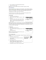
1.


Select


and


enter


the


Networking


menu.


2.


If


you


not


connected


to


your


utility


netw

Connected’


screen


appears.


3.


Use


UP


or


DOWN


to


select


one


of


the


following:


‘Auto’


enables


an


automatic


scan


for


the


channel.


‘All’


searches


all


channels.


‘Channel’


If


you


know


your


channel


number


enter


it


here


(numbers


1


to


26).


can


use


UP


or


DOWN


the


LED


light


is


green.


ete.


If


you


experience


company.


Summary of Contents for GES2181

Page 1: ...Energy Saving Thermostat Insert product picture Instruction Manual Model no GES2181 1...

Page 2: ...2 CONTENTS...

Page 3: ...not place the unit in a bathroom or area of excessive moisture Do not allow the unit to get wet Place the unit in an easy to reach position where you can comfortably reach the buttons and view the sc...

Page 4: ...of the following options Heat Cool or Off Conventional HAVC Heat Emer Emergency Heating Cool or Off Heat pump HVAC 3 Press MENU to confirm your selection and return to the Home screen Note Make sure...

Page 5: ...u Viewing events and me In the Override menu you can choose to accept or reject events and messages and set the thermostat to Vacation to override the programmed settings T 1 Select and enter the Over...

Page 6: ...erature settings for any day of the week 1 Select and enter the Program menu and the screen opposite appears 2 Use UP or DOWN to scroll through the settings and press SYS or FAN to change a setting 3...

Page 7: ...and return to Time Changes the time Date Changes the date Get Network Time If you select and confirm Yes a signal will be sen will be updated on your thermo t out to search for the network time and th...

Page 8: ...he Ne Joined screen opposite 2 Press SELECT to disconnect and the message Are appears 3 Press and hold MENU and INFO simultaneously to co press MENU to exit and return to the pre Note The right LED li...

Page 9: ...i e 8am DURATION The event will last for this duration i e 2 hours Your current energy usage is priced at Level 1 which is currently 2 2 per kilowatt hour A Price A Message Your utility company will s...

Page 10: ...ettings progra med in the thermostat in response to different energy price level Below is a table of for the Price ffset vel LED Indicator Offset in F When ok in the top lor and the other is tri color...

Page 11: ...ed by UL cUL CSA Disconnection means Type 1B Pollution Degree 2 Warning Changes or modifications to this unit not expressly approved by the esponsible for compliance could void the user s authority to...

Page 12: ...12 lse voltage 330V allation please refer to the install Warning Do not connect any of the termi ply Rated Impu For inst ation and wiring diagram under Appendix nals to 110V 220V AC sup...

Page 13: ...common for control circuit and thermostat power input Fan 1st stage cooling 1st stage compressor 2nd stage cooling 2nd stage compressor 1st stage heating Auxiliary heating 2nd stage heating Emergency...

Page 14: ...14 iring diagram for Heat pump system W Aux heating Emergency...

Page 15: ...15 system Wiring diagram for conventional Heat Cool 2010 Computime Limited...

Reviews: