Sentinel 150P installation, operation & maintenance
ci0050 p7/8 issue 5 2014-08-26
Operation
LED indication
3 LEDs, positioned in the middle of the Sentinel's protective
cover (with the product label), provide user indication of AC
power, DC charge and fault conditions:
LED
colour
LED
state
charger condition
blue
AC power condition:
solid on
AC power on
green
DC output and charge condition:
solid on
Float charging
slow flash Ramp to Boost (bulk charge)
fast flash
Boost extension (absorption charge)
solid off
battery check/missing, with output
programmed to be off
red
Faults/warnings:
solid on
AC mains fail and/or charge fail
slow flash DC connection error
fast flash
High volts alarm, low volts alarm, RTC
sensor short or battery missing
solid off
No fault detected
On models with a programmable input, an active input is
indicated by rapid flashing green and red LEDs.
Initial Power-Up
– Commissioning Charge
When powered up for the first time, with both AC and DC
connected, the Sentinel 150P performs an AutoBoost charge
with the boost extension timer is set to 6 hours (regardless
of the profile configuration). This ensures the connected
batteries receive a full commissioning charge.
After completion of this commissioning charge, Sentinel's
boost extension time reverts to the profile's set level (factory
default time is 2 hours).
Float charge operation
Sentinel operates an intelligent, multi-stage battery charge
regime. In normal charging mode, the charger maintains
the battery at a pre-calibrated float voltage (see page 3 -
DC Output Calibration table), while supplying any additional
DC load up to the specified current limit. The Sentinel 150P
has a maximum default current limit of 5A, but the software
configurator allows this to be reduced if required.
When fully charged, a battery will only accept the charge
required to replace internal losses (approx. 1mA per AH of
battery). E.g. for a system with a 1 Amp standing load and a
fully charged 50 AH lead acid battery, Sentinel will typically
supply 1.05 Amps.
AutoBoost operation
AutoBoost mode provides a temporary increase in output
voltage. It may be initiated:
automatically on battery low voltage (programmable level,
factory default 12.0V / 24.0V)
automatically on expiry of a time interval since the last
AutoBoost (programmable level, factory default 28 days)
by an operator-controlled, panel-mounted momentary
push switch, if the Sentinel has a switch input configured
for "AutoBoost initiate".
Sentinel charges the batteries in AutoBoost mode for a
preset time (also programmable), after which it automatically
returns to float mode.
AutoBoost provides charge equalisation between cells,
without overcharge, maximising battery capacity, power and
service life.
Battery check
As part of its diagnostic process, Sentinel can periodically
check for a 'battery missing' condition by reducing its charge
output and measuring battery voltage.
Sentinel performs a Battery Check:
at power up
at the end of an AutoBoost cycle
periodically, while in float mode (programmable time,
default is every 60 minutes)
On detection of a battery missing fault (voltage below a
programmed threshold, factory default 12V), Sentinel
can be configured to operate the alarm output and/or
maintain/reduce the charge output. It will also carry out
further battery checks every minute until the fault clears.
Time/voltage parameters and responses can be changed
or disabled using the software configurator tool.
The Battery Check feature does not operate during
AutoBoost cycles, and a battery missing condition will inhibit
initialisation of AutoBoost.
Fault Finding, Warranty and Maintenance
Warranty and servicing
Sentinel chargers are supplied with a 2 year warranty on parts
and workmanship.
Maintenance is limited to keeping the charger free from
ingress of dust, dirt or moisture, and ensuring clear air-flow for
ventilation.
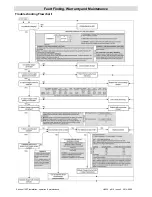
In the event of an operating query or suspected fault, please
consult the sections in this manual, including the trouble-
shooting flowchart on page 8, or contact your supplier for
further advice before returning the charger.
WARNING:
Sentinel battery chargers and
internal components are not user-serviceable.
No attempt should be made to repair the
charger. Any attempt to do so may invalidate
warranties, cause permanent damage to the
charger and connected equipment, and result
in serious personal injury.


