MULTIPLEXER CONTROLLING
3
TP4MD/CD / TP10MS/MD/CD / TP16MS/MD/C
E
N
G
L
IS
H
1. 1-16
Press the buttons 1 - 16 to display the correspon-
ding camera image.
2.
REC
Press the button REC to start recording to the
VCR.
3.
HOLD
Press the button HOLD to freeze all cameras on
the divided screen.
4. PLAY
Press the button PLAY to start the playback from
the VCR.
5. SEQ
Press the button SEQ to control an analogue chan-
nel MON SPOT.
6. MENU
Press the button MENU to display the on-screen
menu.
7. DIRECTION ARROWS
These buttons are used for moving in the menu
and for controlling the pan/tilt camera heads and
zoom lenses in telemetry.
8. ZOOM +/-
By pressing the buttons ZOOM it is possible to
control the digital zoom (PLAY mode only) and the
optical zoom for telemetry.
9. FOCUS +/-
Focus controlling buttons for telemetry
10. IRIS +/-
Iris controlling buttons for telemetry
11. VIEW
After pressing the button VIEW it is possible to se-
lect various types of displaying of the camera
numbers on the screen.
12. MACRO
Press the button MACRO to load the defined mac-
ros.
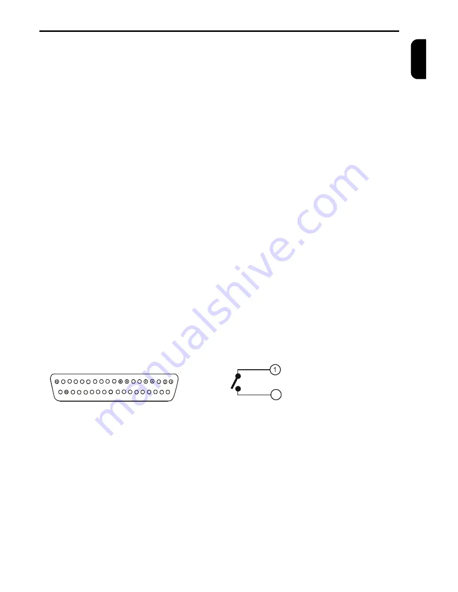
Fig. 3a: D-SUB37M alarm connector
18
17 16
15
14
13
12
11
10
7
6
3
20
21
22
23
24
25
26
27
28
29
30
31
32
33
34
35
37
13. ALARM
Press the button ALARM to display the alarm
status. Press the button again to display the list of
alarm events.
14.AUTO
Press the button AUTO to starts/stop the auto
matic camera switching, according to the pro-
grammed sequence.
15. PRESET
By pressing the button PRESET it is possible to
set up prepositions of the connected devices. This
button has more telemetry functions.
16. IN1 – IN16
Video inputs for cameras 1 – 16.
The video inputs are automatically terminated if the
corresponding video output is left unconnected. If a
device is connected to video out make sure that it
is properly terminated.
17. VCR IN
Use this video input for connecting from VCR.
18. SPOT
Video output to spot monitor.
19. OUT1 – OUT16
Video outputs for cameras 1 – 16.
20. VCR OUT
Video output to VCR.
21. MAIN
Video output to main monitor.
22. MAIN
S-VHS video output to main monitor ( only for col-
our multiplexers ).
23.ALARM
Connector serve for RS 485, RS 232 and CAN in-
terfaces and enables connecting alarm contact
makers, sensors, ect.
24. DC12V
Connector for connecting power supply
(12VDC,
min 700mA)
.
Fig. 3b: Alarm output internal connection
Contact 1
20
Contact 2
(1)
Alarm output – contact 1
(2)
Reserve
(3)
Common input conductor – ground (GND)
(4)
Alarm input 1
(5)
Alarm input 3
(6)
Alarm input 5 (TP10, TP16)
(7)
Alarm input 7 (TP10, TP16)
(8)
Alarm input 9 (TP10, TP16)
(9)
Alarm input 11 (TP16)
(10)
Alarm input 13 (TP16)
(11)
Alarm input 15 (TP16)
(12)
Common input conductor – ground (GND)
(13)
RS 232 RX
(14)
RS 232 TX
(15)
CAN terminating resistance
(16)
CAN_L, connect to twist pair cable conductor
(17)
Common input conductor – ground (GND)
(18)
RS 485 A (+)
(19)
RS 485 terminating to use connect with (18)
(20)
Alarm output – contact 2
(21)
Common input conductor – ground (GND)
(22)
AUX input from VCR
(23)
Alarm input 2
(24)
Alarm input 4
(25)
Alarm input 6 (TP10, TP16)
(26)
Alarm input 8 (TP10, TP16)
(27)
Alarm input 10 (TP10, TP16)
(28)
Alarm input 12 (TP16)
(29)
Alarm input 14 (TP16)
(30)
Alarm input 16 (TP16)
(31)
Common input conductor – ground (GND)
(32)
RS 232 RTS
(33)
RS 232 CTS
(34)
CAN_GND, connect to shielding of the cable
(35)
CAN_H. connect to twist pair cable conductor
(36)
RS 485 B (-)
(37)
CAV_V+, (5V/100mA) – do not connect
Summary of Contents for TP10CD
Page 2: ......


