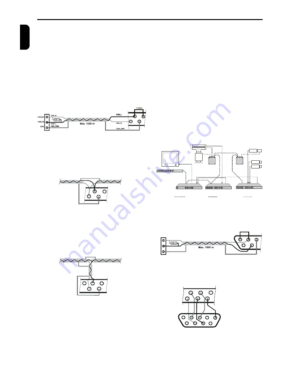
CAN & RS 485, RS 232 INTERFACE
4
TP4MD/CD / TP10MD/CD / TP16MD/CD
E
N
G
L
IS
H
The external devices (PAN/TILT camera heads,
lenses) are connected to the multiplexer using the RS
485 and the CAN interface. The devices are con-
nected with shielded twisted pair cable.
Basic connection of two devices on the CAN bus is
shown at figure 4. (Connection of the multiplexer and
the telemetry receiver TC is used as the example).
Length of the CAN bus can be 1000 m at maximum
and both ends of the bus must be terminated with
120
W
resistor.
Fig. 4: Connection of terminal devices of the CAN bus
35
34
16
15
TC - telemetry receiver
Terminal board K3
CAN Bus
(Shielded twist pair cable)
Multiplexer
Konektor D-SUB
Figure 5 shows the connection of other devices on the
CAN bus. It is possible to connect up to 90 devices in
this way. If you need to connect more devices, it is
necessary to use the CAN bus hub.
Fig. 5: Connection of next device of the CAN bus
CAN_H
CAN_L
CAN_GND
CAN_GND
16
15
35
34
If it is not possible to connect the device directly to the
bus (fig. 5), you can connect it using a stub (fig. 6).
The length of one stub must be 60 m at maximum.
The whole length of all stubs must not exceed 300 m.
Other connection possibilities can be reached using
the CAN bus hub.
Fig. 6: Connection using the stub
CAN_H
CAN_L
CAN_GND
CAN_GND
CAN_GND
Stub
Max. 60 m
16
15
35
34
EXTERNAL KEYBOARD
The external keyboard enables remote controlling of
other external equipment (multiplexers, PAN/TILT
camera heads, lenses) connected to the CAN bus.
You can connect several external keyboards to CAN
bus and control different or the same devices. During
controlling of one device by several keyboards you
are able to operate controlled device by another key-
board five seconds after the last command of the pre-
vious keyboard (it is not possible to control one device
from two keyboards at the same time).
MULTIPLEXERS NETWORKING
Using the external keyboard and auxiliary video
switcher you can simply control several multiplexers
from one external keyboard. So it is possible to control
a group of multiplexers or cameras and watch their
outputs on one monitor. You can use a multiplexer
sequential switcher instead of a video switcher. At
fig. 8 you can see the use of the multiplexer no. 3
analogue sequential switcher as an auxiliary video
switcher. Video outputs of multiplexers no. 1 and 2
lead to video inputs 1 and 2 of the multiplexer no. 3.
For example, when the external keyboard starts to
control multiplexer no. 2, it also sends a command to
the multiplexer no. 3 to display output of the multi-
plexer no. 2 to the monitor. You can use the unused
video inputs of the multiplexer no. 3 for recording or
displaying on a divided monitor screen.
Fig. 8: Multiplexers networking example
TERMINATOR
CAN BUS
VIDEO SIGNAL
LENS, PAN/TILT
TERMINATOR
P/T UNIT
TC
EXTERNAL KEYBOARD
MONITOR
TP4MD
TP16MS
TELEMETRY
RECEIVER
TELEMETRY
RECEIVER
TC
CAMERA
WITH ZOOM LENS
CAMERA
WITH ZOOM LENS
MULTIPLEXER 3
MULTIPLEXER 2
CAMERA
CAMERA
KB 1
TP16CD
MULTIPLEXER 1
Fig. 9: Connection of RS 485 bus
36
18
17
TERM
37
19
B-
A+
B-
A+
GND
Fig. 10: Connection of RS 232 for download
7
2
3
6
1
Multiplexer D-SUB
PC RS 232
14
13
33
32
31
5
9
4
8
Summary of Contents for TP10CD
Page 2: ......


