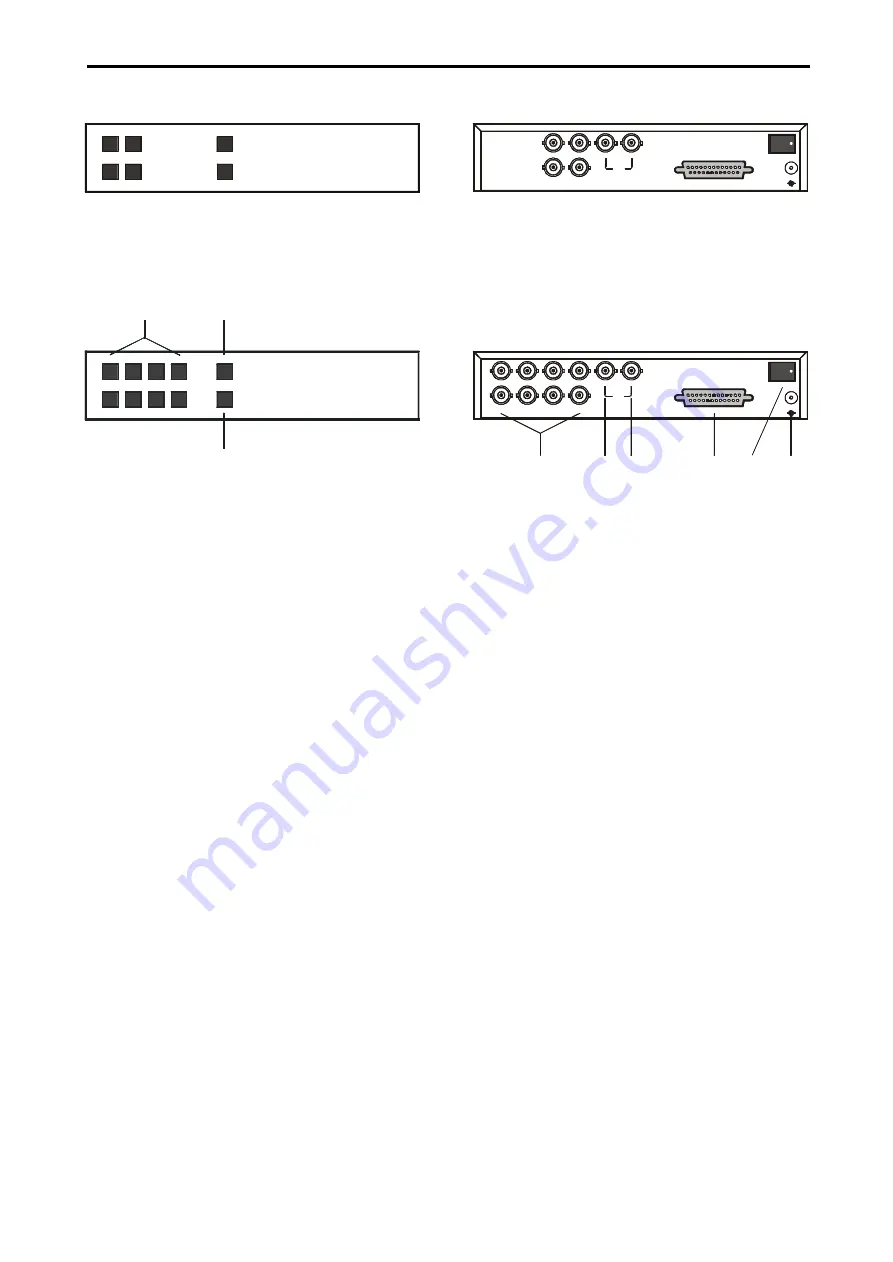
OPERATING ELEMENTS AND FUNCTIONS
VPP404 / VPA404 / VPA408
3
Pict.1: Front panel VPP404 / VPA404
MENU
3
4
1
2
SEQ
4 CHANNEL VIDEO SWITCHER
VPA404
Pict.2: Front panel VPA408
MENU
5
7
6
8
1
3
2
4
SEQ
8 CHANNEL VIDEO SWITCHER
VPA408
1
2
3
1.
1 - 8
Press the button 1 – 8 to display the appro-
priate camera image.
2.
SEQ
Press the button SEQ to start the automatic
camera switching, according to the pro-
grammed sequence.
3. MENU
Press the button MENU to display the control
menu on the screen.
4. IN1 – IN8
Video inputs for cameras 1 – 8.
Pict.3: Back panel VPA404
IN 1
ALARM
IN 3
IN 4
IN 2
POWER
12V
-
+
1
2
M ON
Pict.4: Back panel VPA408
IN 1
ALARM
IN 3
IN 5
IN 7
IN 8
IN 6
IN 4
IN 2
POWER
12V
-
+
4
5
6
7
8
9
1
2
M ON
5. MON 1
Main video output.
6. MON2
Spot video output.
7. ALARM
Connector for connecting alarm inputs and
outputs. This connector enables connecting
of alarm contact makers, sensors, etc.
8. POWER
Press the switch POWER to start the video
switchers.
9. 12V
Connector for connecting power supply.


