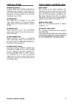
INSTALLATION
SWITCHERS CONTROLLING
VPP404 / VPA404 / VPA408
5
MONITOR OUTPUTS
Outputs VIDEO SWITCHERS and MAIN are
individual video outputs for connecting moni-
tor. For the correct function of the connected
apparatus the signal cables must have the
impedance load of 75
Ω
.
ALARM INPUTS
One alarm input is suitable for one video
input. Alarm loops are connected between
alarm input and common conductor - ground
(GND).
ALARM OUTPUT
Video switchers has its own potentialless
alarm output made of the normally open con-
tacts of the relay.
ALARM CONNECTOR
Alarm connector is used for connecting
alarm inputs and outputs. The connection of
25 outlet connector CANNON is illustrated on
the pictures 5 and 6 (page 4).
POWER SUPPLY INPUT
The video switchers VPP404, VPA404 and
VPA408 are supplied from a uniflow supply
of 12 V. Energy input is 4 W maximum. For
connecting supply voltage is used a concen-
tric connector 5,5 x 2,1 mm. The positive
supply pole is on the inside contact of the
concentric connector, the connector jacket is
the negative pole.
BASIC MODE
After turning on, the video switchers cycli-
cally switches among active cameras accord-
ing to the sequence, which has been set up.
The automatic switching is signaled by the
SEQ light-emitting diode (LED), the camera
displayed on the main video output (MAIN) is
signaled by the diode of the buttons 1 – 8.
MANUAL SWITCHING
Press the corresponding button to display
cameras 1 – 8.
AUTOMATIC SWITCHING
The automatic switching starts by pressing
the button SEQ.
If the video switchers does not start to switch
automatically, check the camera settings in
the menu SEQUENCE and TIME (page 6).


