background image

VIDEO SWITCHERS CONTROLLING (continuation) 

VPP404 / VPA404 / VPA408


6


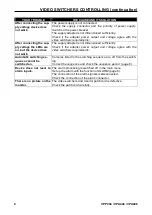
 YOUR TROUBLE 

THE CAUSE AND ITS SOLUTION 

After connecting the sup-
ply voltage device does 
not work. 

The power supply is not connected.


Check  the  supply  connector  and  the  polarity  of  power  supply. 
Switch on the power breaker. 

The supply adapter is not dimensioned sufficiently. 

Check  if  the  adapter  power  output  and  voltage  agree  with  the 
video switchers requirements.


After connecting the sup-
ply voltage the LEDs are 
on, but the device does 
not work. 

The supply adapter is not dimensioned sufficiently. 

Check  if  the  adapter  power  output  and  voltage  agree  with  the 
video switchers requirements. 

Automatic switching se-
quence cannot be 
switched on. 

Cameras listed in the switching sequence are off from the switch-
ing. 

Correct the sequence and check the sequence period  (page 6).


Device  does  not  react  to 
alarm inputs.  

The alarm processing is switched off in the main menu.  

Set up the alarm with the function of ALARM (page 6). 

The connection of the alarm signals is disconnected. 

Check the connection of the alarm connector. 

There is no picture on the 
monitor.  

The video switchers and monitor patchcord is defective. 

Check the patchcord carefully.


Summary of Contents for VPA404

Page 1: ...VIDEO SWITCHER VPP404 VPA404 VPA408 Installation and user manual...

Page 2: ...Y Do not use the unit near water for example near a bath tub or in any area showing evidences of humidity POWER SUPPLY This equipment can be fed only by the type of supply quoted by a production code...

Page 3: ...rammed sequence It is possible to set up cameras which are at the right time available for automatic switching This makes possible to disconnect temporar ily uninteresting or disconnected cameras An o...

Page 4: ...o grammed sequence 3 MENU Press the button MENU to display the control menu on the screen 4 IN1 IN8 Video inputs for cameras 1 8 Pict 3 Back panel VPA404 IN 1 ALARM IN 3 IN 4 IN 2 POWER 12V 1 2 MON Pi...

Page 5: ...serve 19 Reserve 20 Common conductor ground GND 21 Reserve 22 Reserve 23 Reserve 24 Reserve 25 Common conductor ground GND Pict 6 Alarm connector CANNON 25 for VPA408 13 12 11 10 9 8 7 6 5 4 3 14 15 1...

Page 6: ...PLY INPUT The video switchers VPP404 VPA404 and VPA408 are supplied from a uniflow supply of 12 V Energy input is 4 W maximum For connecting supply voltage is used a concen tric connector 5 5 x 2 1 mm...

Page 7: ...RRECT SEQUENCE will appear In that case is necessary to set up cameras in the SEQUENCE menu pro perly TIME SWITCHING PERIOD By using the buttons 1 and 3 1 and 5 by Q8M is possible to prolong or slow d...

Page 8: ...INSTALLATION SWITCHERS CONTROLLING VPP404 VPA404 VPA408 5 after the end of the alarm event in the mode FOLLOW...

Page 9: ...does not work The supply adapter is not dimensioned sufficiently Check if the adapter power output and voltage agree with the video switchers requirements Automatic switching se quence cannot be switc...

Page 10: ......

Page 11: ...ly open Maximum alarm loop impedance 1 k Connector CANNON 25 pin socket ALARM OUTPUT Output 2 low voltage relay contacts Maximum switching voltage 40 V Maximum switching current 0 5 A TEMPERATURE COND...

Page 12: ...2000 COMPUTRONIC Printed in the Czech Republic Producer reserves the right to alternation without prior notice...

Reviews: