QAM Marker
Signal Source
rev1.0.5 August 15, 2017
8
Headend/Hub Installation
Important!
The adjacent QAM channels next to the QAM Marker signal AND the QAM Marker signal must be present
at the ‘Combined RF IN’ (
) before powering on the QAM Marker unit when using the Automatic mode.
The QAM ‘Marker OUT’ (
) is connected to a headend/hub combiner port. If the QAM Marker signal is
NOT present in the RF IN feedback loop, the QAM Marker will continuously ramp the output signal to the
maximum possible level in an attempt to measure itself. This will likely cause the marker to be at levels
that are too high. This can be avoided by making sure the feedback loop for the RF IN Contains both the
adjacent QAM Channels and the Marker signal.
On power up, in automatic mode, the QAM Marker adjusts the ‘Marker OUT’ signal level relative to the
RMS power level of the adjacent QAM channel with the lower RMS power.
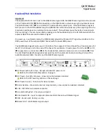
The QAM Marker Signal Source uses 1 3/4 inches of rack space (1 RU) and should have free air space of at
least 1/2 inch above and to the ends of the chassis for ventilation. It needs power from the AC (
) or DC
(
) supply mains, a connection (
) to the headend/hub combiner network, and a connection (
) from
the combined headend/hub signals at test point levels if in Automatic mode (consisting of at least the
available adjacent QAM channel/s and the QAM Marker signal).
AC Power with built-in fuse - Accepts standard IEC power cord.
Refer to the Electrical Safety section on page 4.
DC Power - Dual 48 volt power, screw connection adapter included.
Refer to the DC Powering section on the next page.
DC Power Fuse (2) - Protection for 48 volt power.
Alarm Remote - Connects to internal relay contacts, screw connection adapter included.
LAN - RJ45 Ethernet network connector.
Ground Binding Post - Chassis ground point.
Combined RF IN - Input for adjacent reference QAM channels with Marker signal.
USB - Service port, factory use only.
Marker OUT - QAM Marker signal output.
+ A - + B -
48 VOLTS DC


