CRS-280/280L IF Switch for 1:N Redundancy
Revision -
Connector Pinouts
3–2
MN-CRS-280/280L
3.1.1
CRS-280 Connector Overview
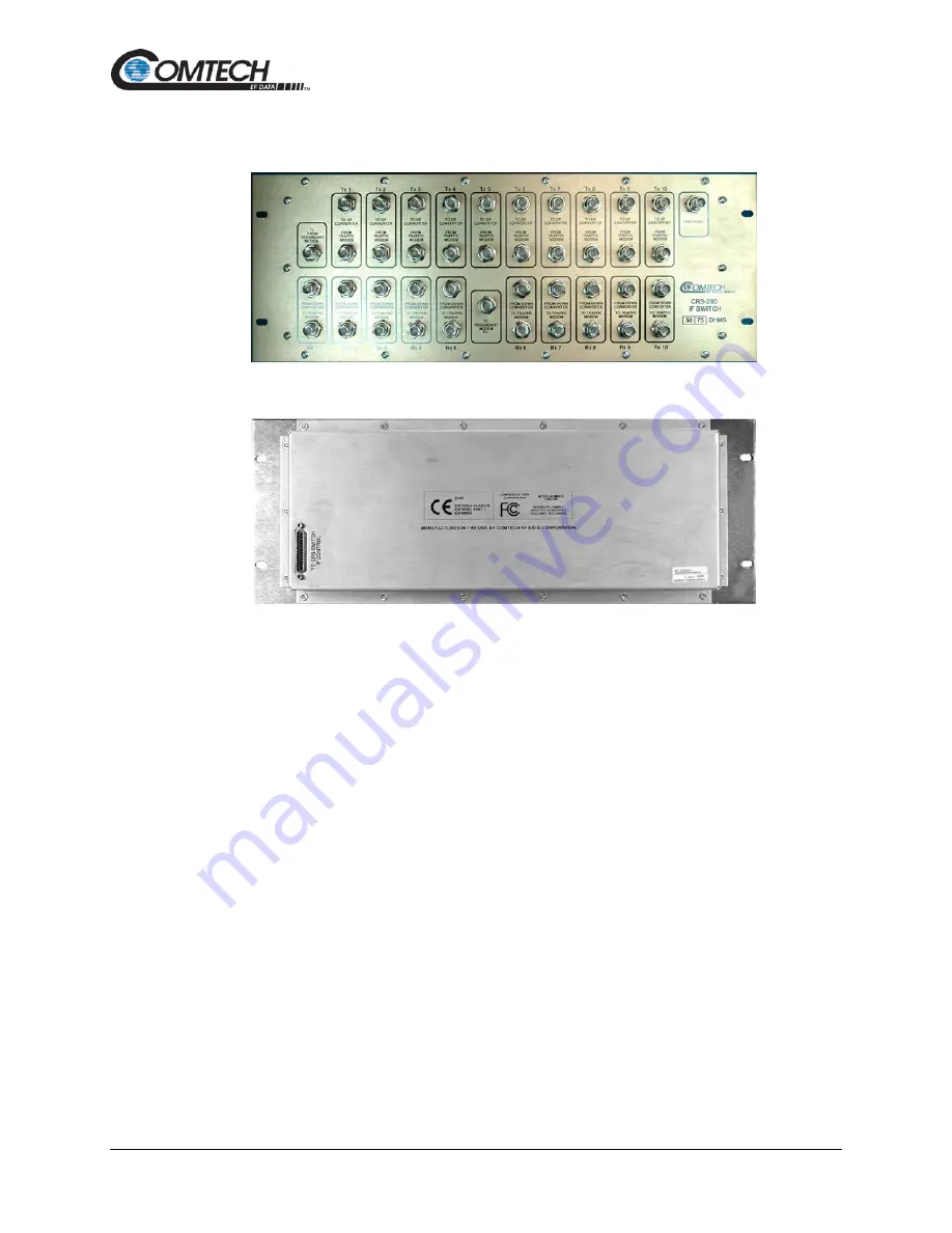
Front Panel View
Rear Panel View
Figure 3-1. CRS-280 Connectors
The front and rear panels of the CRS-280 IF Switch are shown in Figure 3-1.
The front panel connectors provide all necessary connections to connect all equipment internal
and external to the 1:N redundancy setup. The rear panel connector of the CRS-280 provides the
control connector between the CRS-280 and its companion redundancy switch (e.g., CRS-300,
CRS-500, etc.).
Summary of Contents for CRS-280
Page 28: ...CRS 280 280L IF Switch for 1 N Redundancy Revision Introduction 1 14 MN CRS 280 280L Notes ...
Page 68: ...CRS 280 280L IF Switch for 1 N Redundancy Revision Appendix B B 8 MN CRS 280 280L BLANK PAGE ...
Page 69: ......
Page 70: ...2114 WEST 7TH STREET TEMPE ARIZONA 85281 USA 480 333 2200 PHONE 480 333 2161 FAX ...


