Unpacking and Installation
MNC-0300-070
21 of 22
Revision 1
is also used to control the second switch in 1+1 switch around
systems. The pin-outs for the connector can be found in Table
10 (above) of this chapter.
Uplink power control is provided as an option. This connector
accepts a 0-10 VDC input signal proportional to the received
beacon strength. The amplifier can then be configured to adjust
its output power to compensate for rain fades. See addendum
included when option is installed.
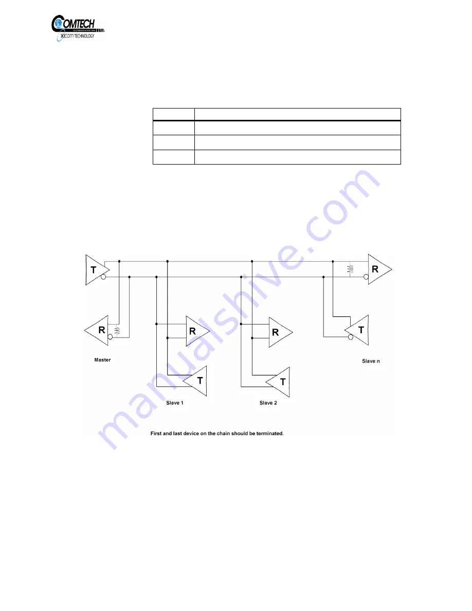
Figure 9, Typical RS-485 2-Wire Duplex Implementation
Table 11, Uplink Power Control Pinouts
Pin No.
Function
1
Uplink power control V in
2
Uplink power control V return
3
Cable shield (ground)
EAR EXPORT CONTROLLED: The information contained in this Manual refers or relates to a product that is subject
to the U.S. Export Administration Regulations (EAR). Transfer of data herein by any means to a Foreign Person,
whether in the U.S. or abroad, may require an export license from the U.S. Department of Commerce.


