background image

Audio Input Connections

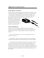
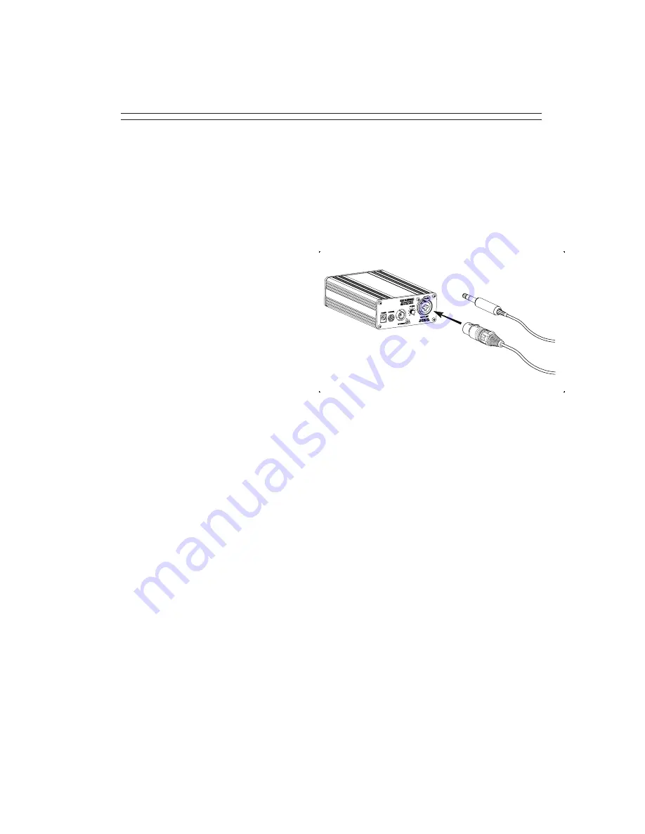
The  BST-75 base station transmitter uses an XLR-3F connector with a
“Combo” phone jack.  The XLR portion of the connector will accept a
true balanced or unbalanced line level signal up to +20 dBm.  The
1/4” phone jack portion of the connector is a dedicated input for a
phantom-powered, two-conductor Electret microphone.  The
HM-100 1/4” behind-the-neck
directional boom microphone
is normally used for language
interpretation, but any two-
conductor Electret microphone
may be used in this input.

Audio Adjustments

In order to ensure the highest possible transmission fidelity, the
transmitter must be modulating at least 50% with normal speech
(0 dB on the VU meter).  This adjustment is made in the following
manner:

a.

  Ensure that the audio source has been optimized for best

signal-to-noise ratio.

b.

  The XLR-3 connector located on the back of the transmitter is

used for line level balanced or unbalanced audio source (0 to +20 dBm).

c.

  Set the AF Gain Control on the back of the base station  to fully

counterclockwise and then, while normal program information is
present, slowly rotate the “LEVEL” control clockwise until the VU
meter on the front panel begins to deflect.  Adjustment should be made
so that normal speech or music deflects the 0dB yellow LED.  Only very
loud speech or music should deflect the VU meter full-scale into the
last red LED.

Page 4

OPERATING INSTRUCTIONS

Summary of Contents for BST-75

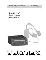
Page 1: ...Synthesized Base Station Transmitter BST 75 OPERATOR S MANUAL 72 76 MHz 357 West 2700 South Salt Lake City Utah 84115 Phone 800 496 3463 Fax 801 484 6906 www comtek com...

Page 2: ...tion Equipment Placement Power Requirements Remote Antenna Screw in Whip Antenna Audio Input Connections Audio Adjustments Audio Processing Circuit Front and Rear Panel Facilities Frequency Informatio...

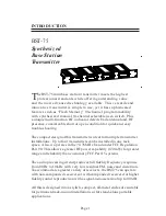
Page 3: ...our transmitters can be installed in one rack space Also it operates in the 72 76 MHz band under FCC Regulation Part 90 This allows a greater RF power capability 120 mW for greater range and reliabili...

Page 4: ...tation or the remote antenna as far as possible from the affected equipment Should you continue to have problems contact COMTEK s Technical Support Services for assistance Power Requirements The BST 7...

Page 5: ...antennas and specialty antennas contact COMTEK s Technical Support Services Integral Screw in Whip Antenna If the BST 75 base station transmitter is to be used outside of the traditional rack mounted...

Page 6: ...he transmitter must be modulating at least 50 with normal speech 0 dB on the VU meter This adjustment is made in the following manner a Ensure that the audio source has been optimized for best signal...

Page 7: ...is however determined by the corresponding de emphasis and equalization used in the receiver In order to accommodate a greater variety of receivers the BST 75 transmitter incorporates the option to o...

Page 8: ...the power is on VU METER Displays the audio level being used for modulation See Audio Adjustment Section ANTENNA INDICATOR Flashes when transmitter detects coaxial cable shorts and open conditions bad...

Page 9: ...tion Section EXTERNAL ANTENNA JACK BNC connector provides a standard 50 ohm RF output for use with an external antenna RF POWER SWITCH Adjusts the RF power output of the transmitter High 120mW Mid 40m...

Page 10: ...3 F 6 01 02 03 04 05 06 07 08 09 10 11 12 13 14 15 16 17 18 19 20 21 22 23 24 25 26 27 28 29 30 31 32 33 34 CHAN FREQ 72 80 MHz 72 82 MHz 72 84 MHz 72 86 MHz 72 88 MHz 72 90 MHz 72 92 MHz 72 94 MHz 72...

Page 11: ...radio receivers to some extent when multiple transmitters are used in the same operating area The RF signals will MIX together generating additional signals If these product frequencies are too close...

Page 12: ...age 10 BST 75 ACCESSORIES Included Accessories 1 C 75 Carrying case 2 BST 75 Operator s manual 3 TWA 75 Telescoping whip antenna 4 AP 12VAC Power adaptor 115V AC Input 5 BST 75 Base station transmitte...

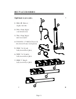
Page 13: ...mote dipole antenna 2 PRA Phase Right coaxial antenna 3 PRA Phase Right antenna mount 4 HM 100 1 4 Behind the neck directional boom microphone 5 RMK 75 4 Quad rack mount face plate 6 RMK 75 2 Double r...

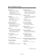
Page 14: ...cy Response 80 Hz to 10 kHz Audio Distortion Less than 0 5 at 80 modulation Modulation Limiter Peak compressor type with high linear overload protection 25 dB Attack time less than 1 ms recovery time...

Page 15: ...ARRANTY OF MERCHANTABILITY OR FITNESS FOR A PARTICULAR PURPOSE OF SUCH EQUIPMENT INCLUDING WITHOUT LIMITATION ANY WARRANTY THAT THE USE OF SUCH EQUIPMENT FOR ANY PURPOSE WILL COMPLY WITH APPLICABLE LA...

Page 16: ...357 West 2700 South Salt Lake City Utah 84115 Phone 800 496 3463 Fax 801 484 6906 www comtek com...

Reviews: