background image

- 7 - 

Tuning 

 
Tuning the 

COM-40VA

 40 Meter Vertical Antenna is straightforward and intuitive. If you use an 

SWR meter or an analyzer at the base of the antenna you will get the most accurate readings in a 
timely fashion. 
 
Since the 2:1 SWR bandwidth of the antenna is wide the adjustment parameters are relatively broad 
and fine adjustment is not usually necessary.  
 

Note: For the purposes of these instructions the term “resonance” or “resonant frequency” is 

defined as the point of lowest SWR and may be used interchangeably. 

 
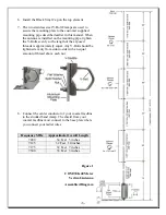
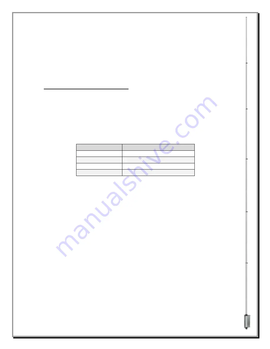
To adjust the low SWR point in the 40 meter band, merely adjust the length of the top tubing 
section in the normal manner, i.e., making it longer lowers the 40 meter resonant frequency and 
shortening it raises the frequency. The top element section is made moveable by loosening the 
element clamp and then sliding the upper element section of the antenna either closer to the base of 
the antenna or farther away depending on whether you want to lower or raise the frequency of 
resonance. Be sure to tighten the clamp after making an antenna length adjustment.  
 

Frequency MHz


Approximate Overall Length


7.000 

34 Feet   5 inches 

7.125 

32 Feet   10 inches 

7.175 

32 Feet   7 inches 

7.300 

33 Feet   3 inches 

 
The approximate lengths shown in this table should also be used when making resonant radials for 
an elevated mount antenna (feedpoint is 3 feet or higher from ground level). For ground mounted 
antennas, resonant radials are not required. 
 
Thank you again for purchasing a Comtek Systems 

COM-40VA

 40 Meter Vertical Antenna. . 


Enjoy your 40 Meter performance while contesting and DXing. 


73


Comtek Systems

     www.comteksystems.com 
Summary of Contents for COM-40VA

Page 1: ...cal Antenna COM 40VA COM 40VA INS Revision 0a COMTEK SYSTEMS 2010 P O Box 1491 Akron OH 44309 1491 USA Phone 800 777 0703 Technical Support and International 330 572 3200 Fax 330 572 3279 E mail Info...

Page 2: ...lement 1 Element Clamp Stainless Steel for 1 5 8 and 1 3 4 antenna elements 2 Element Clamp Stainless Steel for 1 7 8 and 2 antenna elements 2 Stainless Steel Saddle for 2 V Bolts for customer supplie...

Page 3: ...ith the ground around it Use a level as you fill the hole to be sure the pipe is straight Allow to set overnight Your location landscape and ground conditions may require different mounting solutions...

Page 4: ...ineering DXE P8A Penetrox A Anti Oxidant should be used between all antenna element sections Penetrox is an electrical joint compound to affect a substantial electrical connection between metal parts...

Page 5: ...minum element 5 Assemble the vertical sections as shown in Figure 1 using the stainless steel element clamps allowing a four inch overlap between the element sections Slide all the clamps over each se...

Page 6: ...reads is approximately equal Any V Bolt should be tightened evenly from side to side with an equal amount of thread above each nut 8 Connect the center conductor of your coaxial feedline to the studde...

Page 7: ...g it raises the frequency The top element section is made moveable by loosening the element clamp and then sliding the upper element section of the antenna either closer to the base of the antenna or...

Page 8: ...e in writing The above warranties shall not extend to any products or parts thereof which have been subjected to any misuse or neglect damaged by accident rendered defective by reason of improper inst...

Reviews: