background image


81 

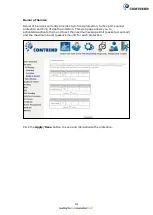
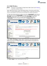
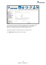
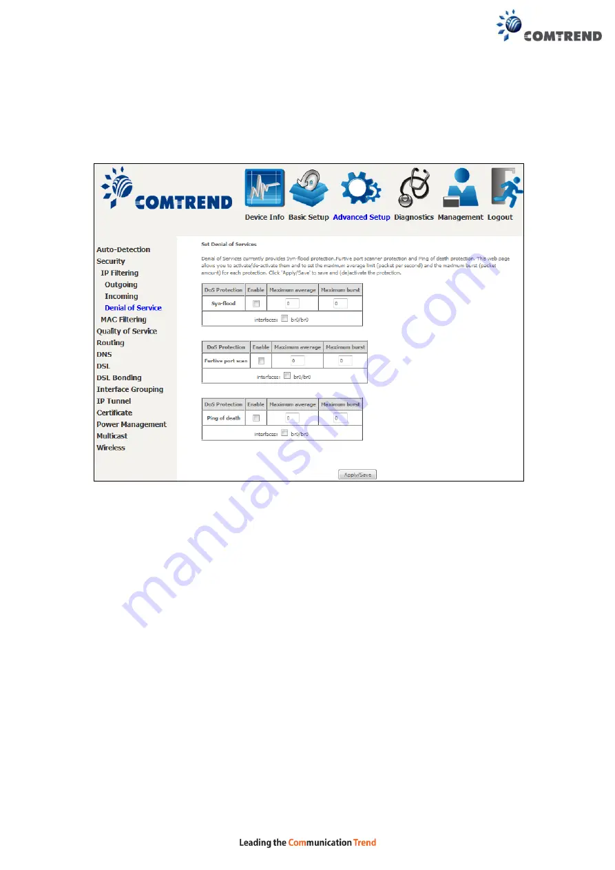
Denial of Service 

 
Denial of Services currently provides Syn-flood protection, furtive port scanner 
protection and Ping of death protection. This web page allows you to 
activate/de-activate them and to set the maximum average limit (packet per second) 
and the maximum burst (packet amount) for each protection.   


Click the 

Apply/Save

 button to save and (de)activate the protection. 


Summary of Contents for NexusLink 3120

Page 1: ...261103 019 applyofkweofkwepqo NexusLink 3120 A VDSL Bonding Router User Manual Version A1 2 May 17 2017 ...

Page 2: ...s e g a wet basement Do not connect the power supply cord on elevated surfaces Allow it to lie freely There should be no obstructions in its path and no heavy items should be placed on the cord In addition do not walk on step on or mistreat the cord Use only the power cord and adapter that are shipped with this device To safeguard the equipment against overheating make sure that all openings in th...

Page 3: ...ipment and receiver Connect the equipment into an outlet on a circuit different from that to which the receiver is connected Consult the dealer or an experienced radio TV technician for help This Class B digital apparatus complies with Canadian ICES 003 To reduce potential radio interference to other users the antenna type and its gain should be so chosen that the equivalent isotropically radiated...

Page 4: ...d are safe for intended operation as described in this manual The further RF exposure reduction can be achieved if the product can be kept as far as possible from the user body or set the device to lower output power if such function is available Déclaration d exposition aux radiationsCet appareil est conforme aux limites d exposition aux radiofréquences portables établies au ISED pour un environn...

Page 5: ...BILITY or FITNESS FOR A PARTICULAR PURPOSE See the GNU General Public License for more details You should have received a copy of the GNU General Public License along with this program If not see http www gnu org licenses NOTE This document is subject to change without notice Protect Our Environment This symbol indicates that when the equipment has reached the end of its useful life it must be tak...

Page 6: ...bor 34 4 8 3 IPv6 Route 35 4 9 CPU MEMORY 36 4 10 NETWORK MAP 37 4 11 WIRELESS 37 4 11 1 Station Info 37 4 11 2 Site Survey 39 CHAPTER 5 BASIC SETUP 41 5 1 WAN SETUP 42 5 1 1 WAN Service Setup 43 5 2 NAT 44 5 2 1 Virtual Servers 44 5 2 2 Port Triggering 46 5 2 3 DMZ Host 48 5 2 4 IP Address Map 49 5 2 5 ALG Pass Through 50 5 3 LAN 51 5 3 1 Lan VLAN Setting 54 5 3 2 LAN IPv6 Autoconfig 55 5 3 3 Sta...

Page 7: ... 9 1 IPv6inIPv4 106 6 9 2 IPv4inIPv6 107 6 10 CERTIFICATE 108 6 10 1 Local 108 6 10 2 Trusted CA 110 6 11 POWER MANAGEMENT 111 6 12 MULTICAST 112 6 13 WIRELESS 114 6 13 1 Basic 2 4GHz 114 6 13 2 Security 2 4GHz 116 6 13 3 WPS 2 4GHz 118 6 13 4 MAC Filter 2 4GHz 121 6 13 5 Wireless Bridge 2 4GHz 123 6 13 6 Advanced 2 4GHz 124 6 13 7 Basic 5GHz 127 6 13 8 WPS 5GHz 129 6 13 9 MAC Filter 5GHz 131 6 13...

Page 8: ...es 152 8 6 3 IP Address 153 8 7 WAKE ON LAN 154 8 8 UPDATE SOFTWARE 155 8 9 REBOOT 156 CHAPTER 9 LOGOUT 157 APPENDIX A FIREWALL 158 APPENDIX B PIN ASSIGNMENTS 161 APPENDIX C SPECIFICATIONS 162 APPENDIX D SSH CLIENT 164 APPENDIX E PRINTER SERVER 165 APPENDIX F CONNECTION SETUP 172 ...

Page 9: ...ccess bandwidth Integrated 5 Giga Ethernet ports support WLAN 802 11n 2 4GHz and 802 11ac 5GHz Frequency bands Therefore NexusLink 3120 is designed for high speed applications and is suitable for triple play services NexusLink 3120 has a USB3 0 host port which provides high speed access for USB devices such as printer server 3G dongle HDD and supports DLNA and samba accessibility ...

Page 10: ... LED Indicators Caution 1 If the device fails to power up or it malfunctions first verify that the power cords are connected securely and then power it on again If the problem persists contact technical support Caution 2 Before servicing or disassembling this equipment disconnect all power cords and telephone lines from their outlets Reset Button Restore the default parameters of the device by pre...

Page 11: ...ort for other devices may be added in future firmware upgrades DSL Port Connect to an ADSL2 2 or VDSL with this RJ11 Port This device contains a micro filter which removes the analog phone signal If you wish you can connect a regular telephone to the same line by using a POTS splitter FRONT PANEL 2 4G WiFi On Off WPS Button Press and release the WiFi WPS button to activate WPS for the 2 4GHz WiFi ...

Page 12: ...at 10 100 Mbps Off Ethernet WAN is not connected Blink In TX RX over 10 100 Mbps ETH 4 to 1 GREEN On Ethernet is connected at 1000 Mbps Off Ethernet is not connected Blink In TX RX over 1000 Mbps ORANGE On Ethernet is connected at 10 100 Mbps Off Ethernet is not connected Blink In TX RX over 10 100 Mbps WPS GREEN On WPS 2 4G WPS enabled and client connected to WLAN Off WPS 2 4G WPS disabled Blink ...

Page 13: ...ing or some traffic is passing through xDSL INTERNET GREEN On IP connected and no traffic detected If an IP or PPPoE session is dropped due to an idle timeout the light will remain green if an ADSL connection is still present Off Modem power off modem in bridged mode or ADSL connection not present In addition if an IP or PPPoE session is dropped for any reason other than an idle timeout the light ...

Page 14: ...access enabled Technical Note During power on the device initializes all settings to default values It will then read the configuration profile from the permanent storage section of flash memory The default attributes are overwritten when identical attributes with different values are configured The configuration profile in permanent storage can be created via the web user interface or telnet user...

Page 15: ...teps involved are similar for most operating systems OS Check your OS support documentation for further details STEP 1 From the Network Connections window open Local Area Connection You may also access this screen by double clicking the Local Area Connection icon on your taskbar Click the Properties button STEP 2 Select Internet Protocol TCP IP and click the Properties button STEP 3 Select Obtain ...

Page 16: ...ck your OS support documentation for further details STEP 1 From the Network Connections window open Local Area Connection You may also access this screen by double clicking the Local Area Connection icon on your taskbar Click the Properties button STEP 2 Select Internet Protocol TCP IP and click the Properties button STEP 3 Change the IP address to the 192 168 1 x 1 x 255 subnet with subnet mask ...

Page 17: ...type http 192 168 1 1 NOTE For local administration i e LAN access the PC running the browser must be attached to the Ethernet and not necessarily to the device For remote access i e WAN use the IP address shown on the Device Information screen and login with remote username and password STEP 2 A dialog box will appear such as the one below Enter the default username and password as defined in sec...

Page 18: ...17 STEP 3 After successfully logging in for the first time you will reach this screen You can also reach this page by clicking on the following icon located at the top of the screen ...

Page 19: ...e options opens a submenu with more selections NOTE The menu items shown are based upon the configured connection s and user account privileges For example user account has limited access to configuration modification Device Info is the first selection on the main menu so it will be discussed first Subsequent chapters will introduce the other main menu options in sequence The Device Info Summary s...

Page 20: ... status Igmp Pxy Shows Internet Group Management Protocol IGMP proxy status Igmp Src Enbl Shows the status of WAN interface used as IGMP source MLD Pxy Shows Multicast Listener Discovery MLD proxy status MLD Src Enbl Shows the status of WAN interface used as MLD source NAT Shows Network Address Translation NAT status Firewall Shows the status of Firewall Status Lists the status of DSL link IPv4 Ad...

Page 21: ... 15 seconds Click Reset Statistics to perform a manual update 4 2 1 LAN Statistics This screen shows data traffic statistics for each LAN interface Heading Description Interface LAN interface s Received Transmitted Bytes Pkts Errs Drops Number of Bytes Number of Packets Number of packets with errors Number of dropped packets ...

Page 22: ...affic statistics for each WAN interface Heading Description Interface WAN interfaces Description WAN service label Received Transmitted Bytes Pkts Errs Drops Number of Bytes Number of Packets Number of packets with errors Number of dropped packets ...

Page 23: ...itted over the interface In Packets Number of packets received over the interface Out Packets Number of packets transmitted over the interface In OAM Cells Number of OAM Cells received over the interface Out OAM Cells Number of OAM Cells transmitted over the interface In ASM Cells Number of ASM Cells received over the interface Out ASM Cells Number of ASM Cells transmitted over the interface In Pa...

Page 24: ...23 4 2 4 xDSL Statistics The xDSL Statistics screen displays information corresponding to the xDSL type The two examples below VDSL ADSL show this variation VDSL ...

Page 25: ...24 ADSL Click the Reset Statistics button to refresh this screen Field Description Mode VDSL VDSL2 Traffic Type ATM PTM Status Lists the status of the DSL link Link Power State Link output power state ...

Page 26: ...transmitted in each data symbol D The interleaver depth I The interleaver block size in bytes N RS codeword size Delay The delay in milliseconds msec INP DMT symbol Super Frames Total number of super frames Super Frame Errors Number of super frames received with errors RS Words Total number of Reed Solomon code errors RS Correctable Errors Total Number of RS with correctable errors RS Uncorrectabl...

Page 27: ...ed Seconds Total UAS Total Number of Unavailable Seconds xDSL BER TEST Click xDSL BER Test on the xDSL Statistics screen to test the Bit Error Rate BER A small pop up window will open after the button is pressed as shown below Click Start to start the test or click Close to cancel the test After the BER testing is complete the pop up window will display as follows ...

Page 28: ...xDSL TONE GRAPH Click Draw Graph on the xDSL Statistics screen and a pop up window will display the xDSL statistics graph including SNR Bits per tone QLN and Hlog of the xDSL line connection as shown below ...

Page 29: ...Destination Flag U route is up reject route G use gateway H target is a host R reinstate route for dynamic routing D dynamically installed by daemon or redirect M modified from routing daemon or redirect Metric The distance to the target usually counted in hops It is not used by recent kernels but may be needed by routing daemons Service Shows the WAN connection label Interface Shows connection in...

Page 30: ...Address Shows the MAC address of host PC Device Shows the connection interface 4 5 DHCP Click DHCP to display all DHCP Leases Field Description Hostname Shows the device host PC network name MAC Address Shows the Ethernet MAC address of the device host PC IP Address Shows IP address of device host PC Expires In Shows how much time is left for each DHCP Lease ...

Page 31: ...ription IPv6 Address Shows IP address of device host PC MAC Address Shows the Ethernet MAC address of the device host PC Duration Shows leased time in hours Expires In Shows how much time is left for each DHCP Lease ...

Page 32: ...ource IP The source IP from which the NAT session is established Source Port The source port from which the NAT session is established Destination IP The IP which the NAT session was connected to Destination Port The port which the NAT session was connected to Protocol The Protocol used in establishing the particular NAT session Timeout The time remaining for the TCP UDP connection to be active ...

Page 33: ...tion Field Description Interface The Source interface from which the IGMP report was received WAN The WAN interface from which the multicast traffic is received Groups The destination IGMP group address Member The Source IP from which the IGMP report was received Timeout The time remaining before the IGMP report expires ...

Page 34: ...enabled Status Connection status of the WAN interface Address IPv6 Address of the WAN interface Prefix Prefix received configured on the WAN interface Device Link local Address The CPE s LAN Address Default IPv6 Gateway The default WAN IPv6 gateway IPv6 DNS Server The IPv6 DNS servers received from the WAN interface configured manually ...

Page 35: ... to display the list of IPv6 nodes discovered Field Description IPv6 Address Ipv6 address of the device s found Flags Status of the neighbor device HW Address MAC address of the neighbor device Device Interface from which the device is located ...

Page 36: ...ck IPv6 Route to display the IPv6 route info Field Description Destination Destination IP Address Gateway Gateway address used for destination IP Metric Metric specified for gateway Interface Interface used for destination IP ...

Page 37: ...36 4 9 CPU Memory Displays the system performance graphs Shows the current loading of the CPU and memory usage with dynamic updates ...

Page 38: ...n of router s wan status and LAN devices Note This graph is unavailable for Internet Explorer users 4 11 Wireless 4 11 1 Station Info This page shows authenticated wireless stations and their status Click the Refresh button to update the list of stations in the WLAN ...

Page 39: ...oint along with the amount of time since packets were transferred to and from each station If a station is idle for too long it is removed from this list Authorized Lists those devices with authorized access SSID Lists which SSID of the modem that the stations connect to RSSI Lists received signal strength of each station in dBm Interface Lists which interface of the modem that the stations connec...

Page 40: ...39 4 11 2 Site Survey The graph displays wireless APs found in your neighborhood by channel 2 4GHz ...

Page 41: ...40 5GHz ...

Page 42: ...41 Chapter 5 Basic Setup You can reach this page by clicking on the following icon located at the top of the screen This will bring you to the following screen ...

Page 43: ... PTM and ETH WAN interface connections here Click Add to create a new Layer 2 Interface see Appendix F Connection Setup NOTE Up to 16 ATM interfaces can be created and saved in flash memory To remove a connection click the Remove button ...

Page 44: ...xId Shows 802 1Q VLAN ID VlanTpid VLAN Tag Protocol Identifier IGMP Proxy Shows Internet Group Management Protocol IGMP Proxy status IGMP Source Shows the status of WAN interface used as IGMP source NAT Shows Network Address Translation NAT status Firewall Shows the Security status IPv6 Shows the WAN IPv6 address MLD Proxy Shows Multicast Listener Discovery MLD Proxy status Mld Source Shows the st...

Page 45: ...fied by Protocol and External port to the internal server with private IP addresses on the LAN side The Internal port is required only if the external port needs to be converted to a different port number used by the server on the LAN side A maximum of 32 entries can be configured To add a Virtual Server click Add The following will be displayed Click Apply Save to apply and save the settings ...

Page 46: ...ver via WAN IP Address External Port Start Enter the starting external port number when you select Custom Server When a service is selected the port ranges are automatically configured External Port End Enter the ending external port number when you select Custom Server When a service is selected the port ranges are automatically configured Protocol TCP TCP UDP or UDP Internal Port Start Enter the...

Page 47: ...tes a TCP UDP connection to a remote party using the Triggering Ports The Router allows the remote party from the WAN side to establish new connections back to the application on the LAN side using the Open Ports A maximum 32 entries can be configured To add a Trigger Port click Add The following will be displayed Click Save Apply to save and apply the settings Consult the table below for field an...

Page 48: ...tically configured Trigger Port End Enter the ending trigger port number when you select custom application When an application is selected the port ranges are automatically configured Trigger Protocol TCP TCP UDP or UDP Open Port Start Enter the starting open port number when you select custom application When an application is selected the port ranges are automatically configured Open Port End E...

Page 49: ...nfigured in the Virtual Servers table to the DMZ host computer To Activate the DMZ host enter the DMZ host IP address and click Save Apply To Deactivate the DMZ host clear the IP address field and click Save Apply Enable NAT Loopback allows PC on the LAN side to access servers in the LAN network via the router s WAN IP ...

Page 50: ...The beginning of the public IP Public End IP The ending of the public IP Remove Remove this rule Click the Add button to display the following Select a Service then click the Save Apply button One to One mapping one local IP to a specific public IP Many to one mapping a range of local IP to a specific public IP Many to many Overload mapping a range of local IP to a different range of public IP Man...

Page 51: ...ough Support ALG Pass through for the listed protocols To allow deny the corresponding ALG protocol select Enable Disable and then click the Save button After reboot the protocol will be added removed from the system module ...

Page 52: ...ettings and then click Apply Save Consult the field descriptions below for more details GroupName Select an Interface Group 1st LAN INTERFACE IP Address Enter the IP address for the LAN port Subnet Mask Enter the subnet mask for the LAN port ...

Page 53: ...lect Enable DHCP server and enter Start and End IP addresses and the Leased Time This setting configures the router to automatically assign IP default gateway and DNS server addresses to every PC on your LAN Setting TFTP Server Enable by ticking the checkbox Then input the TFTP server address or an IP address Enable Automatic Static IP Reservation The Automatic Static IP Reservation function suppo...

Page 54: ... The remote DHCP server will provide the IP address 2ND LAN INTERFACE To configure a secondary IP address tick the checkbox outlined in RED below IP Address Enter the secondary IP address for the LAN port Subnet Mask Enter the secondary subnet mask for the LAN port Ethernet Media Type Configure auto negotiation or enforce selected speed and duplex mode for the Ethernet ports ...

Page 55: ...feature is used Click the Add button to display the following Heading Description Vlan Id Define a specific VLAN ID for this LAN port Pbits Define priority bit for this LAN port To remove an entry tick the corresponding checkbox in the Remove column and then click the Remove button ...

Page 56: ...55 5 3 2 LAN IPv6 Autoconfig Configure the LAN interface settings and then click Save Apply Consult the field descriptions below for more details ...

Page 57: ...ons Heading Description Stateless Use stateless configuration Refresh Time sec The information refresh time option specifies how long a client should wait before refreshing information retrieved from DHCPv6 Stateful Use stateful configuration Start interface ID Start of interface ID to be assigned to dhcpv6 client End interface ID End of interface ID to be assigned to dhcpv6 client Leased Time hou...

Page 58: ...ration Mode Manually configure prefix prefix length preferred lifetime and valid lifetime used in router advertisement Enable ULA Prefix Advertisement Allow RADVD to advertise Unique Local Address Prefix Randomly Generate Use a Randomly Generated Prefix Statically Configure Prefix Specify the prefix to be used Preferred Life Time hour The preferred life time for this prefix Valid Life Time hour Th...

Page 59: ...vices Click the Add button to display the following Click Apply Save to apply and save the settings Heading Description IP Version The IP version used for the neighbor device IP Address Define the IP Address for the neighbor device MAC Address The MAC Address of the neighbor device Associated Interface The interface where the neighbor device is located ...

Page 60: ...59 5 3 4 UPnP Select the checkbox provided and click Apply Save to enable UPnP protocol ...

Page 61: ...rk from active scans set the wireless network name also known as SSID and restrict the channel set based on country requirements Click the Apply Save button to apply the selected wireless options Consult the table below for descriptions of these options Option Description Enable Wireless A checkbox that enables or disables the wireless LAN interface When selected a set of basic wireless options wi...

Page 62: ...etwork name SSID stands for Service Set Identifier All stations must be configured with the correct SSID to access the WLAN If the SSID does not match that user will not be granted access BSSID The BSSID is a 48 bit identity used to identify a particular BSS Basic Service Set within an area In Infrastructure BSS networks the BSSID is the MAC Media Access Control address of the AP Access Point and ...

Page 63: ...tings using the Web User Interface see the table below Select SSID Select the wireless network name from the drop down menu SSID stands for Service Set Identifier All stations must be configured with the correct SSID to access the WLAN If the SSID does not match that client will not be granted access Network Authentication This option specifies whether a network key is used for authentication to t...

Page 64: ...ryption keys are generated and used by the source station and the destination station to alter frame bits thus avoiding disclosure to eavesdroppers Under shared key authentication each wireless station is assumed to have received a secret shared key over a secure channel that is independent from the 802 11 wireless network communications channel Encryption Strength This drop down list box will dis...

Page 65: ...s the wireless LAN interface When selected a set of basic wireless options will appear Hide Access Point Select Hide Access Point to protect the access point from detection by wireless active scans To view and connect to available wireless networks in Windows open Connect to a Network by clicking the network icon or in the notification area If the access point is hidden it will not be listed there...

Page 66: ...P Access Point and in Independent BSS or ad hoc networks the BSSID is generated randomly Priority Sets priority level to SSID from 0 3 Packet flow with high priority SSID will be processed in advance if congestion occurs Wireless Guest Virtual Access Points This router supports multiple SSIDs called Guest SSIDs or Virtual Access Points To enable one or more Guest SSIDs select the checkboxes in the...

Page 67: ...elected The options shown here allow you to configure security features of the wireless LAN interface Please see 6 13 3 for WPS setup instructions Click Apply Save to implement new configuration settings Please see 6 13 for MAC Filter Wireless Bridge and Advanced Wireless features ...

Page 68: ...ch your local time Clicking on the checkbox in the Enable field allows the user to select all none entries for Enabling Disabling Click Add to display the following screen See below for field descriptions Click Apply Save to add a time restriction User Name A user defined label for this restriction Browser s MAC Address MAC address of the PC running the browser Other MAC Address MAC address of ano...

Page 69: ...ype Exclude or Include Tick the Exclude radio button to deny access to the websites listed Tick the Include radio button to restrict access to only those listed websites Then click Add to display the following screen Enter the URL address and port number then click Apply Save to add the entry to the URL filter URL Addresses begin with www as shown in this example ...

Page 70: ...69 A maximum of 100 entries can be added to the URL Filter list ...

Page 71: ...igital media like pictures music and video to other LAN devices from the digital media server Insert the USB drive into the USB host port on the back of the router Click Enable on board digital media server a dropdown list of directories found on the USB driver will be available for selection Select media path from the drop down list or manually modify the media library path and click Apply Save t...

Page 72: ... the user to share files on the storage device Different levels of user access can be configured after samba security mode is enabled This page also displays storage devices attached to the USB host Display after storage device attached for your reference ...

Page 73: ...4 USB Speed This page allows you to enable disable USB 3 0 device support Note Enabling USB 3 0 can cause interference with the built in 2 4GHz wireless radio It is advised leaving the default value as USB 2 0 ...

Page 74: ...ection function is used for CPE to detect WAN service for either ETHWAN or xDSL interfaces The feature is designed for the scenario that requires only one WAN service in different applications The Auto Detection page simply provides a checkbox allowing users to enable or disable the feature Check the checkbox to display the following configuration options ...

Page 75: ...service provider for PPP service detection Select a LAN as WAN Ethernet port for auto detect Select the Ethernet Port that will be used as ETH WAN during auto detection For models with ETH WAN port only ETH WAN port is available to be used as WAN port ...

Page 76: ...s to meet their own requirement and also reduce the detection cycle WAN services list for PTM mode A maximum of 7 WAN services with corresponding VLAN ID 1 indicates no VLAN ID is required for the service are required to be configured for ADSL VDSL PTM mode and ETHWAN The services will be detected in order Users can modify the 7 pre configured services and select disable to ignore any of the servi...

Page 77: ...to meet their deployed requirements Auto Detection status and Restart The Auto detection status is used to display the real time status of the Auto detection feature The Restart button is used to detect all the WAN services that are either detected by the auto detection feature or configured manually by users The following window will pop up upon clicking the Restart button Click the OK button to ...

Page 78: ...ETHWAN port is not detected the Auto Detection for ETHWAN will be configured to the 4th LAN port by default and allows it to be configured for any LAN port as well 3 For cases in which both the DSL port and ETHWAN port are plugged in at the same time the DSL WAN will have priority over ETHWAN For example the ETHWAN port is plugged in with a WAN service detected automatically and then the DSL port ...

Page 79: ...ual IP packets to pass the filter all conditions must be fulfilled NOTE This function is not available when in bridge mode Instead MAC Filtering performs a similar function OUTGOING IP FILTER By default all outgoing IP traffic is allowed but IP traffic can be blocked with filters To add a filter to block some outgoing IP traffic click the Add button On the following screen enter your filter criter...

Page 80: ... range Destination IP address Enter destination IP address Destination Port port or port port Enter destination port number or range INCOMING IP FILTER By default all incoming IP traffic is blocked but IP traffic can be allowed with filters To add a filter to allow incoming IP traffic click the Add button On the following screen enter your filter criteria and then click Apply Save Consult the tabl...

Page 81: ...urce IP address Source Port port or port port Enter source port number or range Destination IP address Enter destination IP address Destination Port port or port port Enter destination port number or range At the bottom of this screen select the WAN and LAN Interfaces to which the filter rule will apply You may select all or just a subset WAN interfaces in bridge mode or without firewall enabled a...

Page 82: ...ve port scanner protection and Ping of death protection This web page allows you to activate de activate them and to set the maximum average limit packet per second and the maximum burst packet amount for each protection Click the Apply Save button to save and de activate the protection ...

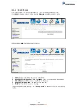
Page 83: ...s FORWARDED means that all MAC layer frames will be FORWARDED except those matching the MAC filter rules BLOCKED means that all MAC layer frames will be BLOCKED except those matching the MAC filter rules The default MAC Filtering Global policy is FORWARDED It can be changed by clicking the Change Policy button Choose Add or Remove to configure MAC filtering rules The following screen will appear w...

Page 84: ... Type PPPoE IPv4 IPv6 AppleTalk IPX NetBEUI IGMP Destination MAC Address Defines the destination MAC address Source MAC Address Defines the source MAC address Frame Direction Select the incoming outgoing packet interface WAN Interfaces Applies the filter to the selected bridge interface ...

Page 85: ...to activate QoS QoS and DSCP Mark are defined as follows Quality of Service QoS This provides different priority to different users or data flows or guarantees a certain level of performance to a data flow in accordance with requests from Queue Prioritization Default Differentiated Services Code Point DSCP Mark This specifies the per hop behavior for a given flow of packets in the Internet Protoco...

Page 86: ...sed for QoS setup In ATM mode a maximum of 16 queues can be configured In PTM mode a maximum of 8 queues can be configured For each Ethernet interface a maximum of 8 queues can be configured For each Ethernet interface a maximum of 8 queues can be configured Please see the screen on the following page ...

Page 87: ...86 ...

Page 88: ...tion is disabled in the Wireless Page queues related to wireless will not take effect This function follows the Differentiated Services rule of IP QoS You can create a new Queue entry by clicking the Add button Enable and assign an interface and precedence on the next screen Click Save Reboot on this screen to activate it Click Add to display the following screen Name Identifier for this Queue ent...

Page 89: ...each precedence level Queues of equal precedence will be scheduled based on the algorithm Queues of unequal precedence will be scheduled based on SP Shaping Rate Specify a shaping rate limit to the defined queue Click Apply Save to apply and save the settings ...

Page 90: ...89 6 3 1 2 Wlan Queue Displays the list of available wireless queues for WMM and wireless data transmit priority ...

Page 91: ... an entry from the list click Remove This screen creates a traffic class rule to classify the upstream traffic assign queuing priority and optionally overwrite the IP header DSCP byte A rule consists of a class name and at least one logical condition All the conditions specified in the rule must be satisfied for it to take effect Click Apply Save to save and activate the rule ...

Page 92: ... MAC Mask This is the mask used to decide how many bits are checked in the Destination MAC Address Classification Results Specify Egress Interface Choose the egress interface from the available list Specify Egress Queue Choose the egress queue from the list of available for the specified egress interface Mark Differentiated Service Code Point The selected Code Point gives the corresponding priorit...

Page 93: ...orts traffic shaping of the Ethernet interface Input the shaping rate and burst size to enforce QoS rule on each interface If Shaping Rate is set to 1 it means no shaping and Burst Size will be ignored Click Apply Save to apply and save the settings ...

Page 94: ...ut ineffective 6 4 1 Default Gateway The default gateway interface list can have multiple WAN interfaces served as system default gateways but only one will be used according to the priority with the first being the highest and the last one the lowest priority if the WAN interface is connected Priority order can be changed by removing all and adding them back in again Click Apply Save to apply and...

Page 95: ... After clicking Add the following will display IP Version Select the IP version to be IPv4 Destination IP address prefix length Enter the destination IP address Interface Select the proper interface for the rule Gateway IP Address The next hop IP address Metric The metric value of routing After completing the settings click Apply Save to add the entry to the routing table ...

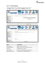
Page 96: ...te one On the following screen complete the form and click Apply Save to create a policy Field Description Policy Name Name of the route policy Physical LAN Port Specify the port to use this route policy Source IP IP Address to be routed Use Interface Interface that traffic will be directed to Default Gateway IP IP Address of the default gateway ...

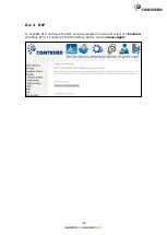
Page 97: ...96 6 4 4 RIP To activate RIP configure the RIP version operation mode and select the Enabled checkbox for at least one WAN interface before clicking Save Apply ...

Page 98: ...igured Static DNS server IP addresses must be entered DNS Server Interfaces can have multiple WAN interfaces served as system DNS servers but only one will be used according to the priority with the first being the highest and the last one the lowest priority if the WAN interface is connected Priority order can be changed by removing all and adding them back in again Click Apply Save to save the n...

Page 99: ...a dynamic DNS service click Add The following screen will display Click Apply Save to save your settings Consult the table below for field descriptions Field Description D DNS provider Select a dynamic DNS provider from the list Hostname Enter the name of the dynamic DNS server Interface Select the interface from the list Username Enter the username of the dynamic DNS server Password Enter the pas...

Page 100: ...n name and IP address pairs desired to be resolved by the DSL router Choose Add or Remove to configure a DNS Entry The entries will become active after save reboot Enter the domain name and IP address that needs to be resolved locally and click the Add Entry button ...

Page 101: ...he CPE gets answers from the DNS server it replies to the LAN clients Configure DNS proxy with the default setting when the PC gets an IP via DHCP the domain name Home will be added to PC s DNS Suffix Search List and the PC can access route with Comtrend Home Click Apply Save to apply and save the settings ...

Page 102: ... Mbps Megabits per second G Dmt Downstream 12 Mbps Upstream 1 3 Mbps G lite Downstream 4 Mbps Upstream 0 5 Mbps T1 413 Downstream 8 Mbps Upstream 1 0 Mbps ADSL2 Downstream 12 Mbps Upstream 1 0 Mbps AnnexL Supports longer loops but with reduced transmission rates ADSL2 Downstream 24 Mbps Upstream 1 0 Mbps AnnexM Downstream 24 Mbps Upstream 3 5 Mbps VDSL2 Downstream 100 Mbps Upstream 60 Mbps ...

Page 103: ...o upstream Bitswap Enable Enables adaptive handshaking functionality SRA Enable Enables Seamless Rate Adaptation SRA Select DSL LED behavior Normal TR 68 compliant Select this option for DSL LED to operate normally See menu 2 2 LED Indicator Off DSL LED will always be OFF G997 1 EOC xTU R Serial Number Select Equipment Serial Number or Equipment MAC Address to use router s serial number or MAC add...

Page 104: ...mapping groups with appropriate LAN and WAN interfaces using the Add button The Remove button removes mapping groups returning the ungrouped interfaces to the Default group Only the default group has an IP interface To add an Interface Group click the Add button The following screen will appear It lists the available and grouped interfaces Follow the instructions shown onscreen ...

Page 105: ...local DHCP server will decline and send the requests to a remote DHCP server by mapping the appropriate LAN interface This will be turned on when Interface Grouping is enabled For example imagine there are 4 PVCs 0 33 0 36 0 37 0 38 VPI VCI 0 33 is for PPPoE while the other PVCs are for IP set top box video The LAN interfaces are ETH1 ETH2 ETH3 and ETH4 ...

Page 106: ... 36 i e for set top box use only LAN side clients can get IP addresses from the CPE s DHCP server and access the Internet via PPPoE 0 33 If a set top box is connected to ETH1 and sends a DHCP request with vendor ID Video the local DHCP server will forward this request to the remote DHCP server The Interface Grouping configuration will automatically change to the following 1 Default ETH2 ETH3 and E...

Page 107: ...d by the tunnel deployment Associated WAN Interface Select the WAN interface to be used by the tunnel Associated LAN Interface Select the LAN interface to be included in the tunnel Manual Automatic Select automatic for point to multipoint tunneling manual for point to point tunneling IPv4 Mask Length The subnet mask length used for the IPv4 interface 6rd Prefix with Prefix Length Prefix and prefix...

Page 108: ...escription Tunnel Name Input a name for the tunnel Mechanism Mechanism used by the tunnel deployment Associated WAN Interface Select the WAN interface to be used by the tunnel Associated LAN Interface Select the LAN interface to be included in the tunnel Manual Automatic Select automatic for point to multipoint tunneling manual for point to point tunneling AFTR Address of Address Family Translatio...

Page 109: ...is valid 6 10 1 Local CREATE CERTIFICATE REQUEST Click Create Certificate Request to generate a certificate signing request The certificate signing request can be submitted to the vendor ISP ITSP to apply for a certificate Some information must be included in the certificate signing request Your vendor ISP ITSP will ask you to provide the information they require and to provide the information in ...

Page 110: ... Do not abbreviate State Province Name The state or province where your organization is located It cannot be abbreviated Country Region Name The two letter ISO abbreviation for your country IMPORT CERTIFICATE Click Import Certificate to paste the certificate content and the private key provided by your vendor ISP ITSP into the corresponding boxes shown below Enter a certificate name and click the ...

Page 111: ...ncryption decryption Its purpose is to sign and issue certificates in order to prove that these certificates are valid Click Import Certificate to paste the certificate content of your trusted CA The CA certificate content will be provided by your vendor ISP ITSP and is used to authenticate the Auto Configuration Server ACS that the CPE will connect to Enter a certificate name and click Apply to i...

Page 112: ...111 6 11 Power Management This screen allows for control of hardware modules to evaluate power consumption Use the buttons to select the desired option click Apply and check the response ...

Page 113: ...112 6 12 Multicast Input new IGMP or MLD protocol configuration fields if you want modify default values shown Then click Apply Save Multicast Precedence Select precedence of multicast packets ...

Page 114: ...s that the IGMP router waits to receive a response to a Group Specific Query message The last member query interval is also the amount of time in seconds between successive Group Specific Query messages The default last member query interval is 10 seconds Robustness Value The robustness variable is a way of indicating how susceptible the subnet is to lost packets IGMP can recover from robustness v...

Page 115: ...ong other things you can enable or disable the wireless LAN interface hide the network from active scans set the wireless network name also known as SSID and restrict the channel set based on country requirements Click Apply Save to configure the basic wireless options Consult the table below for descriptions of these options ...

Page 116: ...s the wireless network name SSID stands for Service Set Identifier All stations must be configured with the correct SSID to access the WLAN If the SSID does not match that user will not be granted access BSSID The BSSID is a 48 bit identity used to identify a particular BSS Basic Service Set within an area In Infrastructure BSS networks the BSSID is the MAC Media Access Control address of the AP A...

Page 117: ...from the drop down menu SSID stands for Service Set Identifier All stations must be configured with the correct SSID to access the WLAN If the SSID does not match that client will not be granted access Network Authentication This option specifies whether a network key is used for authentication to the wireless network If network authentication is set to Open then no authentication is provided Desp...

Page 118: ... unauthorized access such as eavesdropping in this case the capture of wireless network traffic When data encryption is enabled secret shared encryption keys are generated and used by the source station and the destination station to alter frame bits thus avoiding disclosure to eavesdroppers Under shared key authentication each wireless station is assumed to have received a secret shared key over ...

Page 119: ...ailable in Open WPA PSK WPA2 PSK and Mixed WPA2 WPA PSK network authentication modes Other authentication modes do not use WPS so they must be configured manually To configure security settings with WPS follow the procedures below I Setup Step 1 Enable WPS by selecting Enabled from the drop down list box shown Step 2 Set the WPS AP Mode Configured is used when the NexusLink 3120 will assign securi...

Page 120: ...e push button function A typical WPS client screenshot is shown below as an example Now go to Step 7 part III Check Connection to check the WPS connection IIb WPS PIN CONFIGURATION Using this method security settings are configured with a personal identification number PIN The PIN can be found on the device itself or within the software The PIN may be generated randomly in the latter case To obtai...

Page 121: ...t For Configured mode the client must be configured as an Enrollee For Unconfigured mode the client must be configured as the Registrar This is different from the External Registrar function provided in Windows Vista The figure below provides an example of a WPS client PIN function in progress III CHECK CONNECTION Step 5 If the WPS setup method was successful you will be able access the wireless A...

Page 122: ...l stations must be configured with the correct SSID to access the WLAN If the SSID does not match that user will not be granted access MAC Restrict Mode Disabled MAC filtering is disabled Allow Permits access for the specified MAC addresses Deny Rejects access for the specified MAC addresses MAC Address Lists the MAC addresses subject to the MAC Restrict Mode A maximum of 60 MAC addresses can be a...

Page 123: ...122 Enter the MAC address in the box provided and click Apply Save ...

Page 124: ...scription Bridge Restrict Selecting Disabled disables wireless bridge restriction which means that any wireless bridge will be granted access Selecting Enabled or Enabled Scan enables wireless bridge restriction Only those bridges selected in the Remote Bridges list will be granted access Click Refresh to update the station list when Bridge Restrict is enabled Remote Bridges MAC Address Enter the ...

Page 125: ...ld set the wakeup interval for clients in power save mode set the beacon interval for the access point set XPress mode and set whether short or long preambles are used Click Apply Save to set new advanced wireless options Field Description Band Supports both 2 4GHz and 5GHz bands NL 3120 adapts to all 802 11x series up to the latest 802 11ac standard Legacy client devices may support only 2 4GHz 5...

Page 126: ...econds the traffic must be below the PPS value below before the Rx Chain Power Save feature activates itself RX Chain Power Save PPS The maximum number of packets per seconds that can be processed by the WLAN interface for a duration of Quiet Time described above before the Rx Chain Power Save feature activates itself 54g Rate Drop down menu that specifies the following fixed rates Auto Default Us...

Page 127: ...sence of an access point By default network devices passively scan all RF channels listening for beacons coming from access points Before a station enters power save mode the station needs the beacon interval to know when to wake up to receive the beacon and learn whether there are buffered frames at the access point Global Max Clients The maximum number of clients that can connect to the router X...

Page 128: ... from active scans set the wireless network name also known as SSID and restrict the channel set based on country requirements Click Apply Save to configure the basic wireless options Consult the table below for descriptions of these options Option Description Enable Wireless A checkbox that enables or disables the wireless LAN interface When selected a set of basic wireless options will appear ...

Page 129: ...s must be configured with the correct SSID to access the WLAN If the SSID does not match that user will not be granted access BSSID The BSSID is a 48 bit identity used to identify a particular BSS Basic Service Set within an area In Infrastructure BSS networks the BSSID is the MAC Media Access Control address of the AP Access Point and in Independent BSS or ad hoc networks the BSSID is generated r...

Page 130: ...lick Apply Save A When enabled in configured mode use Push button or PIN to allow client connection To activate Push button click on the Add Enrollee PBC button or use the 5G Wifi On Off WPS button on the front panel Personal Identification Number PIN has to be read from either a sticker or the display on the client wireless device ...

Page 131: ...130 B When enabled in unconfigured mode input the Device PIN displayed to your wireless client to initiate the PIN connection ...

Page 132: ...d to set allowed MAC addresses and click the associated button for each interface to enable disable the MAC address control After clicking the Add button the following screen appears Enter the MAC address in the box provided and click Apply Save ...

Page 133: ...enter the corresponding MAC address of the designated wireless devices and click Apply Save to apply the wireless bridge settings Feature Description MAC Address MAC address of the other wireless station Passphrase Passphrase of the other wireless station VLAN Assign VLAN Group to this bridge RSSI received signal strength of the other station ...

Page 134: ...tion of a specific channel Bandwidth Select the bandwidth used on the 5G interface 80MHz is selected by default DTIM Interval Delivery Traffic Indication Message DTIM is also known as Beacon Rate The entry range is a value between 1 and 65535 A DTIM is a countdown variable that informs clients of the next window for listening to broadcast and multicast messages When the AP has buffered broadcast o...

Page 135: ... the beacon and learn whether there are buffered frames at the access point Beamforming Transmission Enable beamforming signal enhance for wireless transmission DTIM Interval Delivery Traffic Indication Message DTIM is also known as Beacon Rate The entry range is a value between 1 and 65535 A DTIM is a countdown variable that informs clients of the next window for listening to broadcast and multic...

Page 136: ...the following icon located at the top of the screen 7 1 Diagnostics Individual Tests The first Diagnostics screen is a dashboard that shows overall connection status Click the Diagnostics Menu item on the left side of the screen to display the individual connections ...

Page 137: ...he full configuration list At least one option must be enabled for 802 1ah WAN Interface Select layer 2 WAN interface for outgoing OAM packets OAM ID OAM Identification number Auto Event Supports OAM auto event Variable Retrieval Supports OAM variable retrieval Link Events Supports OAM link events Remote Loopback Supports OAM remove loopback Active mode Supports OAM active mode ...

Page 138: ...nd Point Identifier Local MEP VLAN ID VLAN IP used for Local Maintenance End point Click CCM Transmission to enable CPE sending Continuity Check Message CCM continuously Remote MEP ID Maintenance association End Point Identifier for the remote receiver To perform Loopback Linktrace OAM test enter the Target MAC of the destination and click Send Loopback or Send Linktrace button Target MAC MAC Addr...

Page 139: ...e ETH or Layer 3 connection is down the uptime will stop incrementing If the service is restored the counter will reset and start from 0 A Bridge interface will follow the DSL or ETH timer The ClearAll button will restart the counters from 0 or show Not Connected if the interface is down ...

Page 140: ...139 7 4 Ping Input the IP address hostname and click the Ping button to execute ping diagnostic test to send the ICMP request to the specified host ...

Page 141: ...140 7 5 Trace Route Input the IP address hostname and click the TraceRoute button to execute the trace route diagnostic test to send the ICMP packets to the specified host ...

Page 142: ...tenance functions and processes 8 1 Settings This includes Backup Settings Update Settings and Restore Default screens 8 1 1 Backup Settings To save the current configuration to a file on your PC click Backup Settings You will be prompted for backup file location This file can later be used to recover settings on the Update Settings screen as described below ...

Page 143: ...Browse to search for the file then click Update Settings to recover settings 8 1 3 Restore Default Click Restore Default Settings to restore factory default settings After Restore Default Settings is clicked the following screen appears Close the browser and wait for 2 minutes before reopening it It may also be necessary to reconfigure your PC IP configuration to match any new settings ...

Page 144: ...er support the reset to default If the Reset button is continuously pressed for more than 10 seconds the current configuration data will be erased If the Reset button is continuously pressed for more than 60 seconds the boot loader will erase all configuration data saved in flash memory and enter bootloader mode ...

Page 145: ...m Log as shown below circled in Red STEP 2 Select desired options and click Apply Save Consult the table below for detailed descriptions of each system log option Option Description Log Indicates whether the system is currently recording events The user can enable or disable event logging By default it is disabled To enable it select the Enable radio button and then click Apply Save ...

Page 146: ...ebug level messages Emergency is the most serious event level whereas Debugging is the least important For instance if the log level is set to Debugging all the events from the lowest Debugging level to the most critical level Emergency level will be recorded If the log level is set to Error only Error and the level above will be logged Display Level Allows the user to select the logged events and...

Page 147: ...ple Network Management Protocol SNMP allows a management application to retrieve statistics and status from the SNMP agent in this device Select the Enable radio button configure options and click Save Apply to activate SNMP ...

Page 148: ...on Description Enable TR 069 Tick the checkbox to enable OUI serial The serial number used to identify the CPE when making a connection to the ACS using the CPE WAN Management Protocol Select MAC to use the router s MAC address as serial number to authenticate with ACS or select serial number to use router s serial number Inform Disable Enable TR 069 client on the CPE Inform Interval The duration ...

Page 149: ...rface used by TR 069 client Choose Any_WAN LAN Loopback or a configured connection Connection Request Authentication Tick the checkbox to enable User Name Username used to authenticate an ACS making a Connection Request to the CPE Password Password used to authenticate an ACS making a Connection Request to the CPE URL IP address and port the ACS uses to connect to router Enable STUN Client STUN Se...

Page 150: ... tick the corresponding checkbox choose your preferred time server s select the correct time zone offset and click Apply Save NOTE Internet Time must be activated to use See 5 5 Parental Control The internet time feature will not operate when router is in bridged mode since the route would not be able to connect to the NTP timeserver ...

Page 151: ...unt is typically utilized by Carrier ISP technicians for maintenance and diagnostics The user account is typically utilized by End Users to view configuration settings and statistics with limited ability to configure certain settings The apuser account is typically utilized by End Users to view configuration settings and statistics with limited ability to configure wireless settings Use the fields...

Page 152: ...151 Note Passwords may be as long as 16 characters but must not contain a space Click Save Apply to continue ...

Page 153: ...vices option limits or opens the access services over the LAN or WAN The access services available are HTTP SSH TELNET SNMP HTTPS FTP TFTP and ICMP Enable a service by selecting its dropdown listbox Click Apply Save to activate ...

Page 154: ...stem applications listed in the Service Control List beside ICMP Click the Add button to display the following Configure the address and subnet of the management station permitted to access the local management services and click Save Apply IP Address IP address of the management station Subnet Mask Subnet address for the management station Interface Access permission for the specified address all...

Page 155: ...r device that is going to be woken up must support Wake on LAN LAN Interface Select the LAN interface to send the Wake on LAN packet MAC Address Specify the MAC address of the device that is going to be woken up Click Send WoL magic packet to the Broadcast address if the WoL packets should be sent to the broadcast address Click the Wake Up button to send the magic packet out to the LAN interface ...

Page 156: ...ase All Router will be restored to factory default configuration after software upgrade STEP 3 Enter the path and filename of the firmware image file in the Software File Name field or click the Browse button to locate the image file STEP 4 Click the Update Software button once to upload and install the file NOTE The update process will take about 2 minutes to complete The device will reboot and t...

Page 157: ...To save the current configuration and reboot the router click Reboot NOTE You may need to close the browser window and wait for 2 minutes before reopening it It may also be necessary to reset your PC IP configuration ...

Page 158: ... log out from the device simply click the following icon located at the top of your screen When the following window pops up click the OK button to exit the router Upon successful exit the following message will be displayed ...

Page 159: ... allowed By setting up one or more filters specific packet types coming from the LAN can be dropped Example 1 Filter Name Out_Filter1 Protocol TCP Source IP address 192 168 1 45 Source Subnet Mask 255 255 255 0 Source Port 80 Dest IP Address NA Dest Subnet Mask NA Dest Port NA This filter will Drop all TCP packets coming from the LAN with IP Address Subnet Mask of 192 168 1 45 24 having a source p...

Page 160: ...2 168 1 45 24 and a destination port in the range of 6060 to 7070 All other incoming packets on this interface are DROPPED MAC LAYER FILTER These rules help in the filtering of Layer 2 traffic MAC Filtering is only effective in Bridge mode After a Bridge mode connection is created navigate to Advanced Setup Security MAC Filtering in the WUI Example 1 Global Policy Forwarded Protocol Type PPPoE Des...

Page 161: ...times Example User Name FilterJohn Browser s MAC Address 00 25 46 78 63 21 Days of the Week Mon Wed Fri Start Blocking Time 14 00 End Blocking Time 18 00 With this rule a LAN device with MAC Address of 00 25 46 78 63 21 will have no access to the WAN on Mondays Wednesdays and Fridays from 2pm to 6pm On all other days and times this device will have access to the outside Network ...

Page 162: ...in Name Description 1 BI_DA Bi directional pair A 2 BI_DA Bi directional pair A 3 BI_DB Bi directional pair B 4 BI_DC Bi directional pair C 5 BI_DC Bi directional pair C 6 BI_DB Bi directional pair B 7 BI_DD Bi directional pair D 8 BI_DD Bi directional pair D ...

Page 163: ... WLAN Interface Standard IEEE802 11b g n Encryption 64 128 bit Wired Equivalent Privacy WEP Channels 11 US Canada 13 Europe 14 Japan Data Rate Up to 300Mbps WEP Yes WPA Yes IEEE 802 1x Yes MAC Filtering Yes ATM Attributes RFC 2684 RFC 1483 Bridge Route RFC 2516 PPPoE RFC 2364 PPPoA RFC 1577 IPoA PVCs 16 AAL type AAL5 ATM service class UBR CBR VBR ATM UNI support UNI 3 1 4 0 OAM F4 F5 Yes Managemen...

Page 164: ... and MAC address filtering Access Control QoS IP QoS SP WFQ WRR for QoS Per PVC packet level QoS Environment Condition Operating temperature 0 40 degrees Celsius Relative humidity 5 95 non condensing Dimensions 280 mm W x 35 mm H x 210 mm D Kit Weight 1 NexusLink 3120 1 RJ11 cable 1 RJ45 cable 1 power adapter 1 2 kg NOTE Specifications are subject to change without notice ...

Page 165: ...t enable SSH access for the LAN or WAN from the Management Access Control Services menu in the web user interface To access the router using the Linux ssh client For LAN access type ssh l root 192 168 1 1 For WAN access type ssh l support WAN IP address To access the router using the Windows putty ssh client For LAN access type putty ssh l root 192 168 1 1 For WAN access type putty ssh l support W...

Page 166: ...es to models with a USB host port STEP 1 Enable Print Server from Web User Interface Select the Enable on board print server checkbox and input Printer name Make and model Click the Apply Save button NOTE The Printer name can be any text string up to 40 characters The Make and model can be any text string up to 128 characters ...

Page 167: ...166 STEP 2 Click the Windows start button Then select Control Panel ...

Page 168: ...167 STEP 3 Select Devices and Printers STEP 4 Select Add a printer ...

Page 169: ...168 STEP 5 Select Add a network wireless or Bluetooth printer STEP 6 Click the Stop button Select The printer that I want isn t listed ...

Page 170: ...put the printer link and click Next http LAN IP 631 printers the name of the printer NOTE The printer name must be the same name inputted in the WEB UI printer server settings as in step 1 STEP 8 Select the manufacturer and model of your printer then click OK ...

Page 171: ...170 STEP 9 The printer has been successfully installed Click the Next button STEP 10 Click Finish or print a test page if required ...

Page 172: ...171 STEP 11 Go to Control Panel All Control Panel Items Devices and Printers to confirm that the printer has been configured ...

Page 173: ... which supports multiple connections over a single interface Note that PPPoA and IPoA connection types are not supported for Ethernet WAN interfaces After adding WAN connections to an interface you must also create an Interface Group to connect LAN WAN interfaces F1 1 ATM Interfaces Follow these procedures to configure an ATM interface NOTE The NexusLink 3120 supports up to 16 ATM interfaces STEP ...

Page 174: ... The maximum allowable burst size of cells that can be transmitted continuously on the VBR service connection Link Type Choose EoA for PPPoE IPoE and Bridge PPPoA or IPoA Connection Mode Default Mode Single service over one connection Vlan Mux Mode Multiple Vlan service over one connection IP QoS Quality of Service QoS status Remove Select items for removal STEP 2 Click Add to proceed to the next ...

Page 175: ...e encapsulations for each xDSL Link Type EoA LLC SNAP BRIDGING VC MUX PPPoA VC MUX LLC ENCAPSULATION IPoA LLC SNAP ROUTING VC MUX STEP 3 Click Apply Save to confirm your choices On the next screen check that the ATM interface is added to the list For example an ATM interface on PVC 0 35 in Default Mode with an EoA Link type is shown below ...

Page 176: ...M interface NOTE The NexusLink 3120 supports up to four PTM interfaces STEP 1 Go to Basic Setup WAN Setup Select PTM Interface from the drop down menu This table is provided here for ease of reference Heading Description Interface WAN interface name DSL Latency Path0 portID 0 PTM Priority Normal or High Priority Preemption ...

Page 177: ... WAN connections to one interface type you must delete existing connections from the other interface type using the remove button Default PTM interface Quality of Service can be configured here including Scheduler Queue Weight and Rate Limit STEP 3 Click Apply Save to confirm your choices On the next screen check that the PTM interface is added to the list For example a PTM interface in Default Mo...

Page 178: ...Go to Basic Setup WAN Setup Select ETHERNET Interface from the drop down menu This table is provided here for ease of reference Heading Description Interface Name WAN interface name Connection Mode Default Mode Single service over one interface Vlan Mux Mode Multiple Vlan services over one interface Remove Select interfaces to remove STEP 2 Click Add to proceed to the next screen ...

Page 179: ...STEP 3 Select an Ethernet port and Click Apply Save to confirm your choices On the next screen check that the ETHERNET interface is added to the list To add a WAN connection go to Section F2 WAN Connections ...

Page 180: ...connections To setup a WAN connection follow these instructions STEP 1 Go to Basic Setup WAN Setup STEP 2 Click Add to create a WAN connection The following screen will display STEP 3 Choose a layer 2 interface from the drop down box and click Next The WAN Service Configuration screen will display as shown below ...

Page 181: ... now follow the instructions specific to the WAN service type you wish to establish This list should help you locate the correct procedure 1 For F2 1 PPP over ETHERNET PPPoE IPv4 2 For F2 2 IP over ETHERNET IPoE IPv4 3 For F2 3 Bridging IPv4 4 For F2 4 PPP over ATM PPPoA IPv4 5 For F2 5 IP over ATM IPoA IPv4 6 For F2 6 PPP over ETHERNET PPPoE IPv6 7 For F2 7 IP over ETHERNET IPoE IPv6 8 Bridging I...

Page 182: ...STEP 1 Select the PPP over Ethernet radio button and click Next For tagged service enter valid 802 1P Priority and 802 1Q VLAN ID For untagged service set 1 to both 802 1P Priority and 802 1Q VLAN ID Select a TPID if VLAN tag Q in Q is used ...

Page 183: ...TEP 2 On the next screen enter the PPP settings as provided by your ISP Click Next to continue or click Back to return to the previous step Click Next to continue or click Back to return to the previous step ...

Page 184: ...Disables NAT and Firewall The device becomes the default gateway and DNS server to the PC through DHCP using the LAN interface IP address The device extends the IP subnet at the remote service provider to the LAN PC i e the PC becomes a host belonging to the same IP subnet The device bridges the IP packets between WAN and LAN ports unless the packet is addressed to the device s LAN IP address The ...

Page 185: ...ension is enabled When Enabled this creates local PPPoE connections to the WAN side Enable this option only if all LAN side devices are running PPPoE clients otherwise disable it The NexusLink 3120 supports pass through PPPoE sessions from the LAN side while simultaneously running a PPPoE client from non PPPoE LAN devices ENABLE IGMP MULTICAST PROXY Tick the checkbox to enable Internet Group Membe...

Page 186: ...nterfaces OR enter static DNS server IP addresses for the system In ATM mode if only a single PVC with IPoA or static IPoE protocol is configured Static DNS server IP addresses must be entered Click Next to continue or click Back to return to the previous step ...
Page 187: ...ary screen shows a preview of the WAN service you have configured Check these settings and click Apply Save if they are correct or click Back to modify them After clicking Apply Save the new service should appear on the main screen ...

Page 188: ...TEP 1 Select the IP over Ethernet radio button and click Next For tagged service enter valid 802 1P Priority and 802 1Q VLAN ID For untagged service set 1 to both 802 1P Priority and 802 1Q VLAN ID Select a TPID if VLAN tag Q in Q is used ...

Page 189: ...tain an IP address automatically radio button to enable DHCP use the DHCP Options only if necessary However if you prefer you can use the Static IP address method instead to assign WAN IP address Subnet Mask and Default Gateway manually Click Next to continue or click Back to return to the previous step ...
Page 190: ...le when NAT is enabled Known as one to one NAT all requests from the same internal IP address and port are mapped to the same external IP address and port An external host can send a packet to the internal host by sending a packet to the mapped external address ENABLE FIREWALL If this checkbox is selected the Security submenu will be displayed on the Advanced Setup menu after reboot If firewall is...

Page 191: ...h base MAC Enable this option to use the router s base MAC address as the MAC address for this WAN interface STEP 4 Choose an interface to be the default gateway Click Next to continue or click Back to return to the previous step ...
Page 192: ...nterfaces OR enter static DNS server IP addresses for the system In ATM mode if only a single PVC with IPoA or static IPoE protocol is configured Static DNS server IP addresses must be entered Click Next to continue or click Back to return to the previous step ...
Page 193: ...ary screen shows a preview of the WAN service you have configured Check these settings and click Apply Save if they are correct or click Back to modify them After clicking Apply Save the new service should appear on the main screen ...

Page 194: ...f this bridge WAN interface as IGMP multicast source Allow as MLD Multicast Source Click to allow use of this bridge WAN interface as MLD multicast source For tagged service enter valid 802 1P Priority and 802 1Q VLAN ID For untagged service set 1 to both 802 1P Priority and 802 1Q VLAN ID Select a TPID if VLAN tag Q in Q is used ...

Page 195: ...s and click Apply Save if they are correct or click Back to return to the previous screen After clicking Apply Save the new service should appear on the main screen NOTE If this bridge connection is your only WAN service the NexusLink 3120 will be inaccessible for remote management or technical support from the WAN ...

Page 196: ...195 F2 4 PPP over ATM PPPoA IPv4 STEP 1 Click Next to continue ...

Page 197: ... continue or click Back to return to the previous step PPP SETTINGS The PPP username and password are dependent on the requirements of the ISP The user name can be a maximum of 256 characters and the password a maximum of 32 characters in length Authentication Method AUTO PAP CHAP or MSCHAP ...

Page 198: ...s LAN IP address The public IP address assigned by the remote side using the PPP IPCP protocol is actually not used on the WAN PPP interface Instead it is forwarded to the PC LAN interface through DHCP Only one PC on the LAN can be connected to the remote since the DHCP server within the device has only a single IP address to assign to a LAN device ENABLE NAT If the LAN is configured with a privat...

Page 199: ...GMP multicast This protocol is used by IPv4 hosts to report their multicast group memberships to any neighboring multicast routers ENABLE IGMP MULTICAST SOURCE Enable the WAN interface to be used as IGMP multicast source Enable WAN interface with base MAC Enable this option to use the router s base MAC address as the MAC address for this WAN interface STEP 3 Choose an interface to be the default g...

Page 200: ...nterfaces OR enter static DNS server IP addresses for the system In ATM mode if only a single PVC with IPoA or static IPoE protocol is configured Static DNS server IP addresses must be entered Click Next to continue or click Back to return to the previous step ...
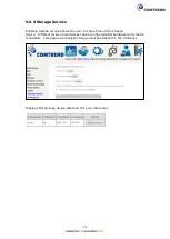
Page 201: ...ary screen shows a preview of the WAN service you have configured Check these settings and click Apply Save if they are correct or click Back to modify them After clicking Apply Save the new service should appear on the main screen ...

Page 202: ...2 Enter the WAN IP settings provided by your ISP Click Next to continue STEP 3 This screen provides access to NAT Firewall and IGMP Multicast settings Enable each by selecting the appropriate checkbox Click Next to continue or click Back to return to the previous step ...
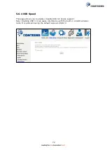
Page 203: ...cket to the mapped external address ENABLE FIREWALL If this checkbox is selected the Security submenu will be displayed on the Advanced Setup menu after reboot If firewall is not necessary this checkbox should not be selected so as to free up system resources for better performance ENABLE IGMP MULTICAST PROXY Tick the checkbox to enable Internet Group Membership Protocol IGMP multicast This protoc...

Page 204: ...next screen STEP 5 Select DNS Server Interface from available WAN interfaces OR enter static DNS server IP addresses for the system In ATM mode if only a single PVC with IPoA or static IPoE protocol is configured Static DNS server IP addresses must be entered Click Next to continue or click Back to return to the previous step ...

Page 205: ...ary screen shows a preview of the WAN service you have configured Check these settings and click Apply Save if they are correct or click Back to modify them After clicking Apply Save the new service should appear on the main screen ...

Page 206: ...adio button Then select IPv6 only from the drop down box at the bottom off the screen and click Next For tagged service enter valid 802 1P Priority and 802 1Q VLAN ID For untagged service set 1 to both 802 1P Priority and 802 1Q VLAN ID Select a TPID if VLAN tag Q in Q is used ...

Page 207: ...206 STEP 2 On the next screen enter the PPP settings as provided by your ISP Click Next to continue or click Back to return to the previous step ...

Page 208: ...the following Allows only one PC on the LAN Disables NAT and Firewall The device becomes the default gateway and DNS server to the PC through DHCP using the LAN interface IP address The device extends the IP subnet at the remote service provider to the LAN PC i e the PC becomes a host belonging to the same IP subnet The device bridges the IP packets between WAN and LAN ports unless the packet is a...

Page 209: ...es Protocol Assignments Internet protocols numbering systems are managed by IANA in conjunction with standards bodies LAUNCH DHCP6C FOR PREFIX DELEGATION IAPD An Identity Association for Prefix Delegation IAPD is a collection of prefixes assigned to a requesting device A requesting device may have more than one IAPD for example one for each of its interfaces A prefix delegating router DHCPv6 serve...

Page 210: ...ing PPPoE clients otherwise disable it The NexusLink 3120 supports pass through PPPoE sessions from the LAN side while simultaneously running a PPPoE client from non PPPoE LAN devices ENABLE MLD MULTICAST PROXY Multicast Listener Discovery MLD is a component of the Internet Protocol Version 6 IPv6 suite MLD is used by IPv6 routers for discovering multicast listeners on a directly attached link muc...

Page 211: ...3 Choose an interface to be the default gateway Also select a preferred WAN interface as the system default IPv6 gateway from the drop down box Click Next to continue or click Back to return to the previous step ...

Page 212: ... or static IPoE protocol is configured Static DNS server IP addresses must be entered Select the configured WAN interface for IPv6 DNS server information OR enter the static IPv6 DNS server Addresses Note that selecting a WAN interface for IPv6 DNS server will enable DHCPv6 Client on that interface Click Next to continue or click Back to return to the previous step ...

Page 213: ...ary screen shows a preview of the WAN service you have configured Check these settings and click Apply Save if they are correct or click Back to modify them After clicking Apply Save the new service should appear on the main screen ...

Page 214: ...on and click Next Then select IPv6 only from the drop down box at the bottom off the screen and click Next For tagged service enter valid 802 1P Priority and 802 1Q VLAN ID For untagged service set 1 to both 802 1P Priority and 802 1Q VLAN ID Select a TPID if VLAN tag Q in Q is used ...

Page 215: ...Static IPv6 address method instead to assign WAN IP address Subnet Mask and Default Gateway manually Enter information provided to you by your ISP to configure the WAN IPv6 settings Notice If Obtain an IPv6 address automatically is chosen DHCP client will be enabled on this WAN interface If Use the following Static IPv6 address is chosen enter the static WAN IPv6 address If the address prefix leng...

Page 216: ...215 Click Next to continue or click Back to return to the previous step ...
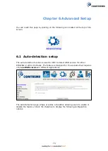
Page 217: ... router DHCPv6 server selects prefixes to be assigned to a requesting router DHCPv6 client upon receiving a request from the client The server can select prefixes for a requesting client by using static and dynamic assignment mechanisms Administrators can manually configure a list of prefixes and associated preferred and valid lifetimes for an IAPD of a specific client that is identified by its DU...

Page 218: ...s checkbox is selected the Security submenu will be displayed on the Advanced Setup menu after reboot If firewall is not necessary this checkbox should not be selected so as to free up system resources for better performance ENABLE MLD MULTICAST PROXY Multicast Listener Discovery MLD is a component of the Internet Protocol Version 6 IPv6 suite MLD is used by IPv6 routers for discovering multicast ...

Page 219: ...To choose an interface to be the default gateway Also select a preferred WAN interface as the system default IPv6 gateway from the drop down box Click Next to continue or click Back to return to the previous step ...
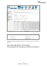
Page 220: ... or static IPoE protocol is configured Static DNS server IP addresses must be entered Select the configured WAN interface for IPv6 DNS server information OR enter the static IPv6 DNS server Addresses Note that selecting a WAN interface for IPv6 DNS server will enable DHCPv6 Client on that interface Click Next to continue or click Back to return to the previous step ...
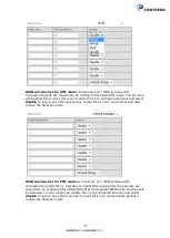
Page 221: ...ary screen shows a preview of the WAN service you have configured Check these settings and click Apply Save if they are correct or click Back to modify them After clicking Apply Save the new service should appear on the main screen ...

Page 222: ...221 F2 8 PPP over ATM PPPoA IPv6 STEP 1 Select IPv6 Only from the drop down box at the bottom of this screen and click Next ...

Page 223: ...222 STEP 2 On the next screen enter the PPP settings as provided by your ISP Click Next to continue or click Back to return to the previous step ...

Page 224: ...ce extends the IP subnet at the remote service provider to the LAN PC i e the PC becomes a host belonging to the same IP subnet The device bridges the IP packets between WAN and LAN ports unless the packet is addressed to the device s LAN IP address The public IP address assigned by the remote side using the PPP IPCP protocol is actually not used on the WAN PPP interface Instead it is forwarded to...

Page 225: ... collection of prefixes assigned to a requesting device A requesting device may have more than one IAPD for example one for each of its interfaces A prefix delegating router DHCPv6 server selects prefixes to be assigned to a requesting router DHCPv6 client upon receiving a request from the client The server can select prefixes for a requesting client by using static and dynamic assignment mechanis...

Page 226: ...iscovering multicast listeners on a directly attached link much like IGMP is used in IPv4 The protocol is embedded in ICMPv6 instead of using a separate protocol ENABLE MLD MULTICAST SOURCE Click to allow use of this WAN interface as Multicast Listener Discovery MLD multicast source Enable WAN interface with base MAC Enable this option to use the router s base MAC address as the MAC address for th...

Page 227: ... or static IPoE protocol is configured Static DNS server IP addresses must be entered Select the configured WAN interface for IPv6 DNS server information OR enter the static IPv6 DNS server Addresses Note that selecting a WAN interface for IPv6 DNS server will enable DHCPv6 Client on that interface Click Next to continue or click Back to return to the previous step ...
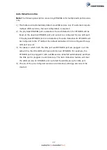
Page 228: ...ary screen shows a preview of the WAN service you have configured Check these settings and click Apply Save if they are correct or click Back to modify them After clicking Apply Save the new service should appear on the main screen ...

Reviews: