background image

22 - Troubleshooting

RocketPort Universal PCI User Guide

: 2000284 Rev. G

Troubleshooting

Bootable CD

Use the following procedure to create a bootable Diagnostic CD.

1.

Copy the 

.iso

 file to a temporary location.

The diagnostic .iso file can be copied from the 

Software and Documentation


CD or you can download the latest version (

Locating the Latest Drivers and 

Documentation

 on Page 6).

2.

Burn the image to a CD-ROM.

Note:

An .iso file cannot be copied onto a CD but must be burned using an 
application that burns the image to the CD. If you do not have an 
application available, you can use a freeware application that is on the 
Comtrol Software and Documentation CD or download it at

ftp://

ftp.comtrol.com/iso/IsoBurner/

.

3.

To run the diagnostic, you will need at least one loopback plug. A loopback 
plug was shipped with the RocketPort Universal PCI. To build a loopback plug, 
see 

DB9 Loopback Plugs

 on Page 13.

4.

To start the diagnostic, reboot your system with the 

Diagnostics

 CD in the 

drive and follow the instructions in the diagnostic.

Running the 
Bootable Diagnostic 
CD

Use the following procedure to run the diagnostics.

Note:

If the diagnostic goes into sleep mode while unattended, press the 

Num Lock


key to activate the screen. Use 

Ctrl/Alt Delete

 to kill the diagnostic process at 

any time.

1.

Insert the bootable CD that contains the diagnostic and restart your machine.

Note:

If the Diagnostic CD does not boot the PC, you may need to change your 
BIOS settings so that the PC can boot from a CD drive.

The diagnostic starts automatically and takes a few moments before the first 
screen appears.

Note:

If the diagnostics did not detect the RocketPort Universal PCI, the 
adapter has a hardware failure, contact Technical support (Page 32).

2.

Press 

Any Key

 at the disclaimer screen to begin the diagnostic.

3.

Press 

Any Key

 at the 

Please Note

 screen about RocketPort ISA.

4.

Press 

Enter

 to 

Are there ISA boards installed? 

in the 

VERIFY TEST

 screen.

5.

Press 

Enter 

to the 

Is this board configured for RS-422? 

query.

Note:

The caution at the bottom of the screen that the RS-232 test will fail 
when run on an RS-422 port.

6.

Press 

Enter

 to the 

Is this board configured for RJ45 cables?

 qquery.

7.

Select from the following options and use the appropriate steps:

Testing a Port or Ports

Stress Testing the RocketPort Universal PCI

Testing a Port or 
Ports

8.

Enter 

1

 to 

4

 and press 

Enter 

to test a port or ports on a specific RocketPort 

Universal PCI or on multiple adapters.

9.

Press 

Enter

 to test ALL ports on the RocketPort Universal PCI or enter the 

port number of a port that you want to test.

10. Follow the instructions on the screen. If you are testing all of the ports and 

have only one loopback plug, you must move it from port to port during the 
test. 

Note:

Port 0 in the diagnostic is Port 1 on the Octacable or interfaces.

The diagnostic will provide hardware status on the 

TESTING SERIAL I/O, 

MODEM CONTROL AND IRQ

 screen.

Summary of Contents for RocketPort

Page 1: ...User Guide ...

Page 2: ...th Edition Rev G October 13 2011 Copyright 2011 Comtrol Corporation All Rights Reserved Comtrol Corporation makes no representations or warranties with regard to the contents of this document or to the suitability of the Comtrol product for any particular purpose Specifications subject to change without notice Some software or features may not be available at the time of publication Contact your r...

Page 3: ...3 DB9 Straight Through Cables 13 DB9 Loopback Plugs 13 RS 232 Female Loopback Plug 13 RS 422 Loopback Plug 13 DB25 Serial Cables and Loopback Plugs 14 DB25 Signals 14 DB25 Null Modem Cables 15 DB25 Null Modem Cables RS 232 15 DB25 Null Modem Cables RS 422 15 DB25 Straight Through Cables RS 232 15 DB25 Loopback Plugs 16 RS 232 Female Loopback Plug 16 RS 422 Female Loopback Plug 16 RS 232 Male Loopb...

Page 4: ...Port or Ports 22 Stress Testing the RocketPort Universal PCI 23 Exiting the Diagnostic 23 If the Diagnostic Fails 23 Troubleshooting Windows Systems 23 Comtrol Utility 24 Using PortMon to Test the Driver Installation 26 Using Test Terminal to Test a Port 29 Troubleshooting Linux Systems 31 lcom 1 31 File Transfer 31 Changing Serial Port Settings stty 31 Setting Up Terminals and Modems mgetty getty...

Page 5: ...lowing interface options Quadcable fanout cable with DB9 or DB25 connectors RJ45 connectors built into the edge of the card 8 Port adapters with the following interface options Octacable fanout cable with DB9 DB25 or RJ45 connectors RJ11 connectors built into the edge of the card Panel mount RS 232 interface box with DB25F connectors Panel mount RS 232 422 interface box with DB25F connectors Panel...

Page 6: ...ard in the host You can use the Software and Documentation CD to locate the latest device drivers and documentation Optionally you can use the links in the following subsection You may want to record the model and serial number of the RocketPort Universal PCI before installing the card in the event you need to call technical support Locating the Latest Drivers and Documentation This table contains...

Page 7: ...Attach the interface or cable to the RocketPort Universal PCI If this is a 4J or 8J installation see Connecting Serial Devices on Page 11 for cabling information after driver installation Attaching a Quadcable or Octacable Interface on Page 7 below Attaching a Panel Interface Box on Page 8 Installing a Rackmount Interface Box on Page 9 Attaching a Quadcable or Octacable Interface Use this procedur...

Page 8: ...the male end of the RocketPort Universal PCI cable to the card and the female end to the connector labeled Host on the interface box Note The male DB25 port labeled Host is reserved for Comtrol use and no user accessible signals are present at this port 3 Tighten the retaining screws Note If you have a 32 port adapter the connector labeled J1 corresponds to Ports 0 through 15 and the connector lab...

Page 9: ...e The cables are interchangeable You may connect either or both cables depending upon the distance between the card and the rack The maximum distance permitted between the interface box and card is 15 feet 4 Optionally for the RM32 RJ45 attach the two cables to the card and the interface The connector labeled J1 corresponds to Host A Ports 0 through 15 and the connector labeled J2 closest to the b...

Page 10: ... Port RS 232 with integrated status LEDs The yellow LEDs show receiving activity The green LEDs show transmitting activity You can use the Troubleshooting section on Page 21 for port testing procedures for your operating system Refer to Connecting Serial Devices on Page 11 for information about connecting serial devices ...

Page 11: ...I DTE Versus DCE Most serial devices except modems are Data Terminal Equipment DTE devices Modems are Data Communication Equipment DCE devices How you build a cable depends on which device your are connecting to DTE or DCE For example you need a null modem cable to connect the COM ports COM1 or COM2 on the computer or the RocketPort Universal PCI ports to printers terminals bar code readers or DNC...

Page 12: ...owing image displays the pinouts for an RS 232 null modem cable Note You can also attach a null modem adapter to one end of a straight through cable to create a null modem cable Pins RS 232 Signals RS 422 Signals 1 CD Not Used 2 RxD TxD 3 TxD RxD 4 DTR Not Used 5 Signal GND Not Used 6 DSR Not Used 7 RTS TxD 8 CTS RxD 9 RI Not Used RS 422 is only available if you are using an RS 422 interface box o...

Page 13: ...rsal PCI are shipped with a a single loopback plug You can use loopback plugs with application software for example Test Terminal to test serial ports Wire the following pins together to build additional plugs or replace a missing loopback plug RS 232 Female Loopback Plug The Quadcable and Octacable use the RS 232 female loopback plug To build a loopback plug for the Quadcable and Octacable wire t...

Page 14: ...xes Quadcable and Octacable fanouts use male connectors This table shows connector information for DB25 connectors Interface Boxes Quad Octacable Pin RS 232 Signal RS 422 Signal RS 232 Signal 1 Not used Not used Not used 2 TxD Not used TxD 3 RxD Not used RxD 4 RTS Not used RTS 5 CTS Not used CTS 6 DSR Not used DSR 7 Signal ground Signal ground Signal ground 8 DCD Not used DCD 9 to 14 Not used Not ...

Page 15: ...signals Note You can also attach a null modem adapter to one end of a straight through cable to create a null modem cable DB25 Straight Through Cables RS 232 Use the following figure if you need to build an RS 232 straight through cable Straight through cables are used to connect modems and other DTE devices For example a straight through cable can be used to connect COM2 of one PC to a modem TxD ...

Page 16: ...male Loopback Plug To build a DB25 loopback plug Surge RS 232 422 switchable interface box for an RS 422 serial connection wire the following pins together Pins 15 to 19 Pins 17 to 25 RS 232 Male Loopback Plug The RS 232 and RS 232 422 interface boxes 8 port and 16 port models use the RS 232 male loopback plug To build a DB25 loopback plug for an RS 232 serial connection wire the following pins to...

Page 17: ...g figures provide pinout information for the RJ45 connectors used on the Octacable interface module Note Ring indicator is not supported on the RJ45 connector RJ45 Null Modem Cables You need a null modem cable to connect to DTE devices For example you can connect one end of a null modem cable to COM2 on one computer and the other end of the null modem cable to COM2 on another computer You can also...

Page 18: ...ight through cable Note If your RJ45 wiring differs from the one shown above adjust the RJ45 pinouts accordingly RJ45 Loopback Plugs A loopback plug is an RJ45 serial port plug with pins wired together You can use loopback plugs with application software for example Test Terminal to test serial ports To build an RJ45 loopback plug wire the following pins together Pins 4 to 5 Pins 1 to 8 Pins 2 to ...

Page 19: ... RS 232 port The following figures provide pinout information for the RJ11 jack plug and receptacle RJ11 Null Modem Cables You need a null modem cable to connect to DTE devices For example you can connect one end of a a null modem cable to COM2 on one computer and the other end of the null modem cable to COM2 on another computer RJ11 Null Modem Cable RS 232 Use the following figure if you need to ...

Page 20: ... computer and the other end of the straight through cable to a modem RJ11 Loopback Plugs A loopback plug is an RJ11 serial port plug with pins wired together You can use it with application software for example Test Terminal to test serial ports To build an RJ11 loopback plug wire these pins together Pins 3 to 4 Pins 1 to 5 to 6 DTR 1 DCD RxD TxD DTR GND Signal DCD RxD TxD GND Signal RJ11 5 4 3 2 ...

Page 21: ...the procedures in the RocketPort Universal PCI Device Driver Installation Guide for Windows or README file packaged with the FreeBSD Linux QNX or SCO OpenServer driver If none of the above work you can refer to one of these subsections Troubleshooting Windows Systems on Page 23 Troubleshooting Linux Systems on Page 31 RocketPort Universal PCI Diagnostics This subsection describes how to create and...

Page 22: ...art your machine Note If the Diagnostic CD does not boot the PC you may need to change your BIOS settings so that the PC can boot from a CD drive The diagnostic starts automatically and takes a few moments before the first screen appears Note If the diagnostics did not detect the RocketPort Universal PCI the adapter has a hardware failure contact Technical support Page 32 2 Press Any Key at the di...

Page 23: ...ng Technical Support 1 Turn off the power and reseat the RocketPort Universal PCI card into the slot 2 Try running the diagnostics again If they fail again you may have a bad port contact Technical Support on Page 32 Troubleshooting Windows Systems If you are using a RocketPort Universal PCI driver on a Windows system and the diagnostic verified that the card is functional you can check the follow...

Page 24: ...errors modem control and status signals In addition it provides you with raw byte input output counts and confirm that the device driver is functioning It can determine if the ports are in use by another application Test Terminal WCOM2 can be used to troubleshoot communications on a port by port basis Using Test Terminal to Test a Port on Page 29 Test Terminal requires a loopback plug You can buil...

Page 25: ...RocketPort Universal PCI User Guide 2000284 Rev G Troubleshooting 25 Troubleshooting 4 Click Install 5 Click Finish 6 Go to Using PortMon to Test the Driver Installation on Page 26 ...

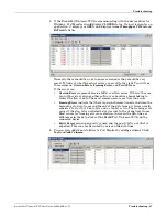
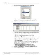
Page 26: ... use PortMon to check whether the RocketPort Universal PCI can communicate through the device driver for Windows If necessary use Comtrol Utility on Page 24 to install PortMon 1 From the Start menu select Programs Comtrol Utilities Port Monitor PMon2 2 Click Add Ports using the icon or Tools Add Ports click Driver ROCKETPORT and click Ok ...

Page 27: ...case you will have to configure either software or hardware handshaking to control the flow of data The most common errors are Overrun errors Framing Errors indicate that there is an synchronization error between the beginning of a data frame and the end of the data frame A frame usually consists of a start bit 8 data bits and a stop bit or two The framing error occurs if the stop bit is not detec...

Page 28: ...eport already exists in an older format Save Active Session button Reports can be opened viewed and re used when needed To open and view a report a Select File Open or the Open Existing Session button The Open Session dialog appears b Locate the session table you want to open and click the Open button Optionally if you want to continue monitoring for an existing session you need to activate the Po...

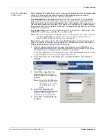
Page 29: ...the interface box and is expected to fail since RS 422 does not have the modem control signals that are present in RS 232 for which this test is designed The following procedure shows how to use Test Terminal to send and receive test data to the serial ports and run a loopback test If necessary install the Comtrol Utility package using Comtrol Utility on Page 24 1 Stop all applications that may be...

Page 30: ...rly and is operational Note If you left Port Monitor running it should show data sent and received and show the average data throughput on the port 6 Select Port Send and Receive Test Data to stop the scrolling data 7 Close Test Terminal If this test successfully completed then the port is operational as expected Note Do NOT forget to restart the communications application ...

Page 31: ...R0 device at 9600 baud 8 n 1 and no parity Changing Serial Port Settings stty Use the following information if you need assistance changing or viewing the baud rate settings To change the baud rate use the following example which changes the baud rate to 19200 stty 19200 dev ttyR0 To view the current serial port settings for ttyR0 enter stty a dev ttyR0 Note Settings changes via stty are only vali...

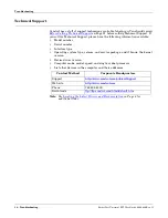
Page 32: ...ion available Model number Serial number Interface type Operating system type release and service package and if Linux the kernel version Device driver version Computer make model speed and single or dual processor List other devices in the computer and their addresses Note See Locating the Latest Drivers and Documentation on Page 6 for additional links Contact Method Corporate Headquarters Suppor...

Reviews: