CH1
CH2
C
15
14
16
17
Thank you for choosing a COMUNELLO AUTOMATION
product.
This manual provides all the detailed information required for
the understanding and correct use of the equipment. It must
be read carefully at the time of purchase and consulted if
there are any doubts regarding its use or when maintenance
is required.
The manufacturer reserves the right to make any modifications
to the item and to this document without prior notice.
WARNINGS
Please read this manual carefully before beginning installation
and carry out the procedures as specified by the manufacturer.
This installation manual is only intended for professional
personnel.
Anything not expressly included in these instructions is
prohibited.
In particular, your attention should be drawn towards the
following warning:
• Disconnect power before making any electrical
connections.
PRODUCT DESCRIPTION
Selector with European key. The INDEX digital selector can
be installed in outdoor environments.
TECHNICAL SPECIFICATIONS
Contact rating
3A 125V AC
IP protection rating
54
Operating temperature
-10°C – 55°C
PRELIMINARY CHECKS
• Check that the item inside the packaging is intact and in
good condition.
• Ensure that the selector is secured to a solid foundation
and is positioned in a location that is easily accessible.
• Ensure that installation is outside the operating zone of the
gate as required by current regulations.
INSTALLATION AND ELECTRICAL CONNECTIONS
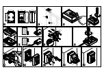
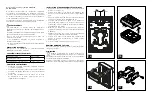
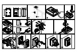
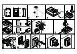
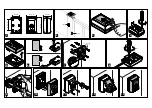
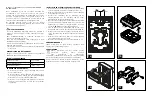
• Disassemble the selector by removing the front cover and
unscrew the screws (Figs. 3-4).
• Turn the key counter-clockwise and remove the lock
assembly as shown in Fig. 5.
• Drill holes in the lower housing of the selector for cable
entry according to the type of installation (Fig. 6).
• Proceed as shown in Figure 7 using rawlplugs (Ø max.
6 mm) and corresponding screws (not included) ensuring
that the printed arrow and the wording “BELOW” are
facing downwards.
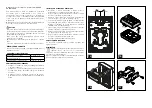
• Connect the cables (Fig. 8) from the control unit to the
corresponding terminal using the diagram in Figure 14.
• Use silicone to seal the cable entry hole and the upper
part of the selector (Fig. 9).
• Turn the key counter-clockwise and reinsert the lock
assembly as shown in Fig. 10.
• Proceed as shown in Figures 11-12.
BOARD REPLACEMENT
If required, replace the card as shown in Figures 15-16-17.
DISPOSAL
A number of components of the item can be recycled
while others, such as electronic components must be
disposed of in accordance with the regulations in force in the
country of installation.
A number of components may contain pollutants that must
not be released into the environment

