
28
COMUNELLO
®Copyright 2016 - All rights reserved
CONTENTS
1
GENERAL PRESCRIPTIONS
1.1
Safety prescriptions
1.2
Installation prescriptions
1.3
Operating prescriptions
2
MODELS AND PRODUCT DESCRIPTION
2.1 Description
2.2
Typical installation
3
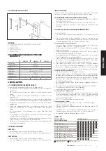
PRODUCT TECHNICAL SPECIFICATIONS
4 INSTALLATION
4.1
Preliminary checks
4.2
Operating limits
4.3
Preparatory work for installation
4.4
Installing the LIMIT barrier system
4.4.1 Installation
4.4.2 Limit stops adjustment
4.4.3 Manual release
5
PREPARATION FOR ELECTRICAL CONNECTIONS
6 TESTING
7
PRODUCT MAINTENANCE
8
SPARE PARTS
9
DISPOSAL OF THE PRODUCT
10
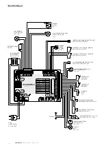
ELECTRONIC CIRCUIT BOARD
10.1 Technical characteristics
10.2 Electrical connections
10.3 Functional characteristics
10.4 Programming
11
WARRANTY
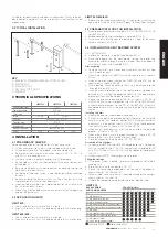
1 GENERAL PRESCRIPTIONS
1.1 SAFETY PRESCRIPTIONS
This installation manual is addressed exclusively
to professionally skilled personnel. Read all the
instructions carefully before starting the installation
procedures. Any operations that are not expressly
set down in these instructions are to be considered
prohibited; improper use may result in damage to
the product and place persons and property at risk.
The manufacturer declines all liability for failure to
observe best technical practices in barrier system
construction and for any possible deformations
that may occur when using the product. Store
this manual in a safe place for future reference.
The design and construction of the devices
fitted on the LIMIT model as well as this manual
are in full compliance with statutory legislation. In
consideration of potential hazards that may arise
during the installation and use of LIMIT, also the
installation procedures must be carried out in full
compliance with the applicable laws, standards
and regulations; specifically:
1.2 INSTALLATION PRESCRIPTIONS
• Before starting the installation procedures
make sure you have any additional devices
and materials that may be required to complete
the LIMIT barrier system in consideration of the
specific application.
• The automation system must not be used until
the transit area has been made safe.
• Dispose of packaging materials in compliance
with local regulations.
1.3 OPERATING PRESCRIPTIONS
• No modifications can be made to any part of the
product unless
specified in this manual. Unauthorized modifications
of the product are likely to lead to malfunctions.
The manufacturer declines all liability for damage
caused by unauthorized modifications.
• The parts of the automation system must never
be immersed in water or other liquids. During
the installation procedures ensure that no solid
objects or liquids penetrate inside the control
unit or other open devices.
• If liquids penetrate any parts of the automation
system, disconnect the electrical power supply
immediately and consult technical service; the
use of LIMIT in such conditions may give rise to
potentially hazardous situations.
• Keep all parts of the LIMIT barrier system away
from heat sources and open flames; exposure
to heat or flames may damage the devices and
cause faults, fire, or hazardous situations.
• When the system remains unused for a long
time, remove the optional battery and store it in
a dry place to avoid the risk of leakage of harmful
substances.
• Connect the control unit exclusively to an electric
power supply line equipped with an efficient
protective earth conductor.
• Any operations that require parts of the LIMIT
barrier system to be opened must be performed
with the control unit and the electrical power
supply disconnected; if the disconnect device
is not clearly visible from where you are working,
attach a warning notice to the effect: “WARNING
- MAINTENANCE IN PROGRESS”.
• In the case of tripping of circuit breakers or
blowing of fuses, find the fault and remedy it
before resetting the circuit breaker or changing
the fuse.
• If the fault cannot be remedied using the
information given in this manual, consult technical
service.
• The device can’t be used by children younger
than 8 years of age and by people with reduced
physical, sensory or mental capabilities, or
without experience or the required knowledge if
not under surveillance or after having received
instructions about the safe use of the device
and the inherent risks in it. Children should not
play with the device. Cleaning and maintenance
should not be carried out by children without
surveillance.
• Children can’t play with the commands of the
automatism. Remote controls should be kept
out of reach of children. It is suggested to
periodically examine the installation in order
to verify the presence of possible damages
to the cables, springs and mechanical parts.
Automation should not be used if it is necessary
a repair intervention.
2 MODELS AND PRODUCTS DESCRIPTION
2.1 DESCRIPTION
Sturdy and easy to install, the LIMIT electromechanical barrier system is
Summary of Contents for LIMIT 500
Page 3: ...3 COMUNELLO Copyright 2016 All rights reserved FIG 2A FIG 2B FIG 3 FIG 4 FIG 3B FIG 5...
Page 5: ...5 COMUNELLO Copyright 2016 All rights reserved FIG 7A FIG 7B FIG 8A FIG 8C FIG 8B FIG 9A...
Page 7: ...7 COMUNELLO Copyright 2016 All rights reserved FIG 13A FIG 13B FIG 14A FIG 14B...
Page 8: ...8 COMUNELLO Copyright 2016 All rights reserved FIG 16A FIG 16B FIG 15...
Page 9: ...9 COMUNELLO Copyright 2016 All rights reserved FIG 17 FIG 18A FIG 18B...
Page 10: ...10 COMUNELLO Copyright 2016 All rights reserved DEFLECTOR FIXING FIG 20A...
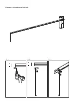
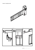
Page 14: ...LIMIT 800 SWING DOWN SUPPORT 45 MIN FIG A FIG C FIG B...
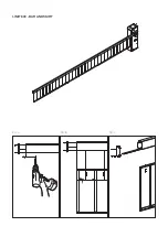
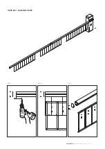
Page 16: ...LIMIT 600 BAR AND SKIRT FIG A FIG C FIG B 110 MIN 110 MIN 200 200...
Page 68: ...NOTES...
Page 69: ...69 COMUNELLO Copyright 2016 All rights reserved NOTES...
Page 70: ...NOTES...
Page 71: ...71 COMUNELLO Copyright 2016 All rights reserved NOTES...


