
30
COMUNELLO
®Copyright 2016 - All rights reserved
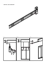
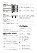
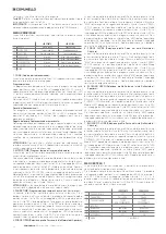
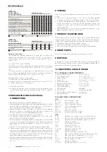
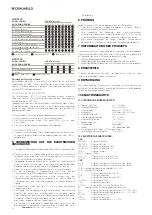
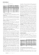
LIMIT 600
BAR ASSEMBLY
LENGTH (meters)
AND SPRING CHOICE
2,0 2,5 3,0 3,5 4,0 4,5 5,0 5,5 6,0
Bar
Bar with bar cover kit
Bar with bar cover kit and led
Bar with swing down support
Bar with bar cover kit and swing down support
Bar with bar cover kit, led and swing down support
Bar with curtain
Bar with upper bar cover and curtain
Bar with upper bar cover, led and curtain
Bar with upper bar cover,
led, curtain and swing down support
Small spring AC 530 Medium spring AC 540
Double spring AC 550
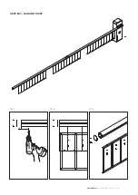
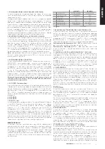
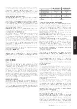
LIMIT 800
BAR ASSEMBLY
LENGTH (meters)
AND SPRING CHOICE
6,0
6,5
7,0
7,5
8,0
Bar
Bar with swing down support
Bar with joint
Medium spring AC 540 Double spring AC 550
Spring pull adjustment:
With the operator released (heading 4.4.3), bring the arm manually to
approximately the mid-point of its excursion (45°) FIG. 14 and release it.
If the arm tends to rise or fall, the spring must be adjusted, rotating it as
shown in FIG. 15.
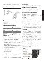
4.4.2 LIMIT SWITCH ADJUSTMENT
The LIMIT barrier system is equipped with electromechanical limit switches
and two bumpers that damp the impact against the limit switches (FIG.
16A).
It is essential to make sure the bumpers are adjusted in such a way that the
limit switches can be operated. Make sure the limit switches trip correctly; if
necessary, adjust the actuator cams as shown in FIG. 16B
Proceed as follows to adjust the bumpers:
• Release the arm as described in heading 4.4.3
• Screw or unscrew the bumper pads on the plate as shown in FIG. 16A
• Secure the bumpers with the locknuts
4.4.3 MANUAL RELEASE
• To release the operator, so that the barrier arm can be moved by hand,
turn the key counter-clockwise and open the front hatch as shown in
FIG. 17.
5 PREPARATION FOR ELECTRICAL
CONNECTIONS
• Remove the front cover using the supplied key (Fig.4)
• Use only double insulated cables (sheathed cables) during the installation
phase for both the connections in AC voltage (230 V) and the ones in
SELV safety extreme low voltage (flashing, photocells).
• Double insulation of cables has to be maintained up to the immediate
proximity of terminals, unsheathing them exclusively in proximity of
terminals and they will have to be bonded by cable ties.
• Use only plastic raceways during the installation phase.
• Use separate raceways for the low voltage wirings (230 V) and for the
ones in SELV safety extreme low voltage.
• Safety extreme low voltage conductors have to be physically separated
(at least 4 mm up in the air) from the ones in AC voltage, or they have
to be adequately isolated with additional insulation with a thickness of at
least 1 mm.
• Use FG7 2x1,5 mm2 cables or an higher category as power cord.
• Provide upstream of the mains supply of the automation a device that
can assure an all-pole disconnection from the electrical grid (with the 3rd
category of overvoltage and with an opening distance of the contacts in
each pole of at least 3 mm), in compliance with the installation rules and
directly connected to the power supply terminals.
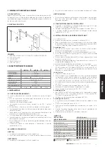
• Bring the wiring to the electronic circuit board located at the top of the
operator, routing the cables along the rear wall as shown in FIG. 18A and
FIG. 18B.
6 TESTING
Perform the following sequence of operations to test the LIMIT barrier
system:
• Check that all the prescriptions in this manual have been followed
scrupulously, with special attention to chapter 1 “General Prescriptions”;
• Using the supplied control or stopping devices (key selector switch,
control pushbuttons or remotes), perform opening, closing and
stopping tests and make sure the barrier responds correctly to the
various commands.
• Check operation of all the system’s safety devices (photocells, safety
edges, emergency stop, etc.), one by one.
7 PRODUCT MAINTENANCE
Maintenance must be carried out at regular intervals by qualified personnel
in compliance with the provisions of statutory legislation and the regulations
in force. LIMIT undergo scheduled servicing at least once every 6 months.
• Disconnect the operator from all power supplies
• Check all the moving parts and renew any worn parts
• Check all parts of the automation system for signs of deterioration
8 SPARE PARTS
Spare parts can be purchased by contacting technical service.
9 DISPOSAL
At the end of its useful life the automation system must be dismantled by
qualified personnel and the materials must be recycled or disposed of in
compliance with the local legislation in force.
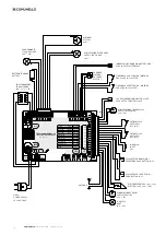
10 ELECTRONIC CIRCUIT BOARD
10.1 TECHNICAL CHARACTERISTICS
• Back-up Battery input:
24 V 7A/h max.
• Flashing light output:
24 V 25 W max.
• Motor 1 output:
24 V motor 50 W max.
• Output LED:
LED strip 24V 50 W max.
• Electric lock output:
24V 15W max.
• Photocells power supply:
24 V 4 W max.
• Indicator light output:
12 V 3 W max.
• Working temperature:
-20 °C + 50 °C
• Radio receiver:
see model
• Transmitters:
18 Bit o Rolling Code
• Max TX codes stored in memory: 120 Remotes
• Board dimensions:
160x105 mm.
10.2 ELECTRICAL CONNECTIONS
CN1:
BATT+24V:
Back-up B input
BATT-24V:
Back-up Battery – input
LAMP+24V:
25W Flashing Light + output
LAMP-24V:
25W Flashing Light – output
MOT1+:
Operator 1 + output.
MOT1-:
Operator 1 – output.
LED+24V:
50 W max LED Strip + Output.
LED-24V:
50 W max LED Strip – Output.
CN2:
SYNC:
Master/Slave Synchronisation Output (Free Contact)
SYNC:
Master/Slave Synchronisation Output (Free Contact)
FOTO+:
Photocells Control and Power Supply (24V~ 5W).
FOTO-:
Common GND input
DS2:
Safety Device 2 Input (NC).
GND:
Common GND input
DS1:
Safety Device 1 Input (NC).
STOP 8K2:
Emergency Stop Input (NC).
GND:
Common GND input.
P PED:
Open only PED command input (NO).
PP:
Open-Close or Close command Pushbutton input (NO).
ELS+:
Electric Lock/Arm Clamp output 24 V (+24V).
ELS-:
Electric Lock/Arm Clamp output 24 V (GND).
24V 5W:
Services output (24V~ 5W)
GND:
Common GND input.
+24VLED:
Indicator light output (+24 V 4 W).
Summary of Contents for LIMIT 500
Page 3: ...3 COMUNELLO Copyright 2016 All rights reserved FIG 2A FIG 2B FIG 3 FIG 4 FIG 3B FIG 5...
Page 5: ...5 COMUNELLO Copyright 2016 All rights reserved FIG 7A FIG 7B FIG 8A FIG 8C FIG 8B FIG 9A...
Page 7: ...7 COMUNELLO Copyright 2016 All rights reserved FIG 13A FIG 13B FIG 14A FIG 14B...
Page 8: ...8 COMUNELLO Copyright 2016 All rights reserved FIG 16A FIG 16B FIG 15...
Page 9: ...9 COMUNELLO Copyright 2016 All rights reserved FIG 17 FIG 18A FIG 18B...
Page 10: ...10 COMUNELLO Copyright 2016 All rights reserved DEFLECTOR FIXING FIG 20A...
Page 14: ...LIMIT 800 SWING DOWN SUPPORT 45 MIN FIG A FIG C FIG B...
Page 16: ...LIMIT 600 BAR AND SKIRT FIG A FIG C FIG B 110 MIN 110 MIN 200 200...
Page 68: ...NOTES...
Page 69: ...69 COMUNELLO Copyright 2016 All rights reserved NOTES...
Page 70: ...NOTES...
Page 71: ...71 COMUNELLO Copyright 2016 All rights reserved NOTES...


