33
COMUNELLO
®Copyright 2016 - All rights reserved
ENGLISH
as described above for LED L1 in the main menu. If you wish to enable
the remote programming function, proceed as follows: ensure you have
enabled Extended Menu 1 (alternate blinking 1 0 1 0 1 0 of menu level
no. 8) and then use the SEL key to select blinking LED L1 and press the
SET key; LED L1 becomes steady on and programming will be completed.
Repeat the procedure if you wish to restore the initial configuration.
2. SELECT PUSHBUTTON PUL = OPEN/CLOSE OR CLOSE:
The control unit allows an NO Pushbutton (PUL CN2 input no. 11) to
be connected to operate the barrier in Open/Close mode. It is however
possible to use this input to connect an NO pushbutton operating in a
different manner. If you wish to enable the “Close only” function, proceed as
follows: ensure you have enabled Extended Menu 1 (alternate blinking 1 0 1
0 1 0 of menu level no. 8) and then use the SEL key to select blinking LED
L2 and press the SET key; LED L2 becomes steady on and the operation
will be completed. Repeat the procedure if you wish to restore the initial
configuration.
Nota:
in Master/Slave applications, if the PUL “Close only” pushbutton has
been selected operation of the PED pushbutton will be enabled for both the
barriers rather than just the Master barrier.
3. AUTOMATIC PROGRAMMING:
The control units allows to make an Automatic Programming (SIMPLIFIED)
in the following way: be sure of having positioned the Barrier open at 45°
and of having enabled the Extended Menu 1 (pointed out by flashing 1
0 1 0 1 of the 8th led), use the SEL key to select the 3rd blinking LED:
pressing continuously SET key, the control unit executes the Auto
Programming procedure by performing a complete opening and closing
cycle (keep the SET key pressed until Auto Programming is finished). During
the programming procedure, the Deceleration cycle is automatically set at
approximately the 15% of the complete cycle.
During the Automatic Programming it is possible to use the button of
the remote control instead of the SET key of the control unit, but only
if previously memorized.
4. FOTOTEST (Photocells test):
The control unit is factory set with the photocells test disabled. If you wish
to enable the photocells test proceed as follows: ensure you have enabled
Extended Menu 1 (blinking 1 0 1 0 1 of LED LEV) and then use the SEL key
to select blinking LED L4 and press the SET key; LED L4 becomes steady
on and the operation will be completed. Repeat the procedure if you wish
to restore the previous configuration.
5. NOT USED:
6. NOT USED:
7. EMERGENCY STOP = 8k2:
The control unit allows the connection of an NC Emergency Stop
pushbutton (CN2 input no.8). However, this input can be converted to
an 8.2k-Ohm resistive input: ensure you have enabled Extended Menu 1
(alternate blinking 1 0 1 0 1 0 of menu level no. 8) and then use the SEL
key to select blinking LED L7 and press the SET key; LED L7 becomes
steady on and programming will be completed. A change in the value read
on the input causes the barrier to stop in the opening stage or reverse its
direction of movement in the closing stage. An additional barrier movement
command will be valid, provided the correct input value is restored, and the
control unit will in any case perform the barrier opening cycle. Repeat the
procedure if you wish to restore the initial configuration.
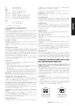
EXTENDED MENU 2
The control unit is supplied by the manufacturer with the facility for direct
selection only from the main menu functions. If you want to enable the
functions described in Extended Menu 2, proceed as follows: select blinking
LED LEV and then press SET twice. The LED will start blinking alternately
1 1 0 1 1 0. This means you have 30 seconds to select the functions of
Extended Menu 2 using the SEL and SET keys; once an additional 30
seconds have elapsed, the control unit reverts to the main menu.
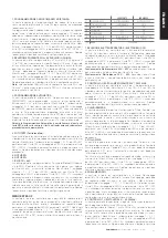
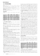
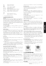
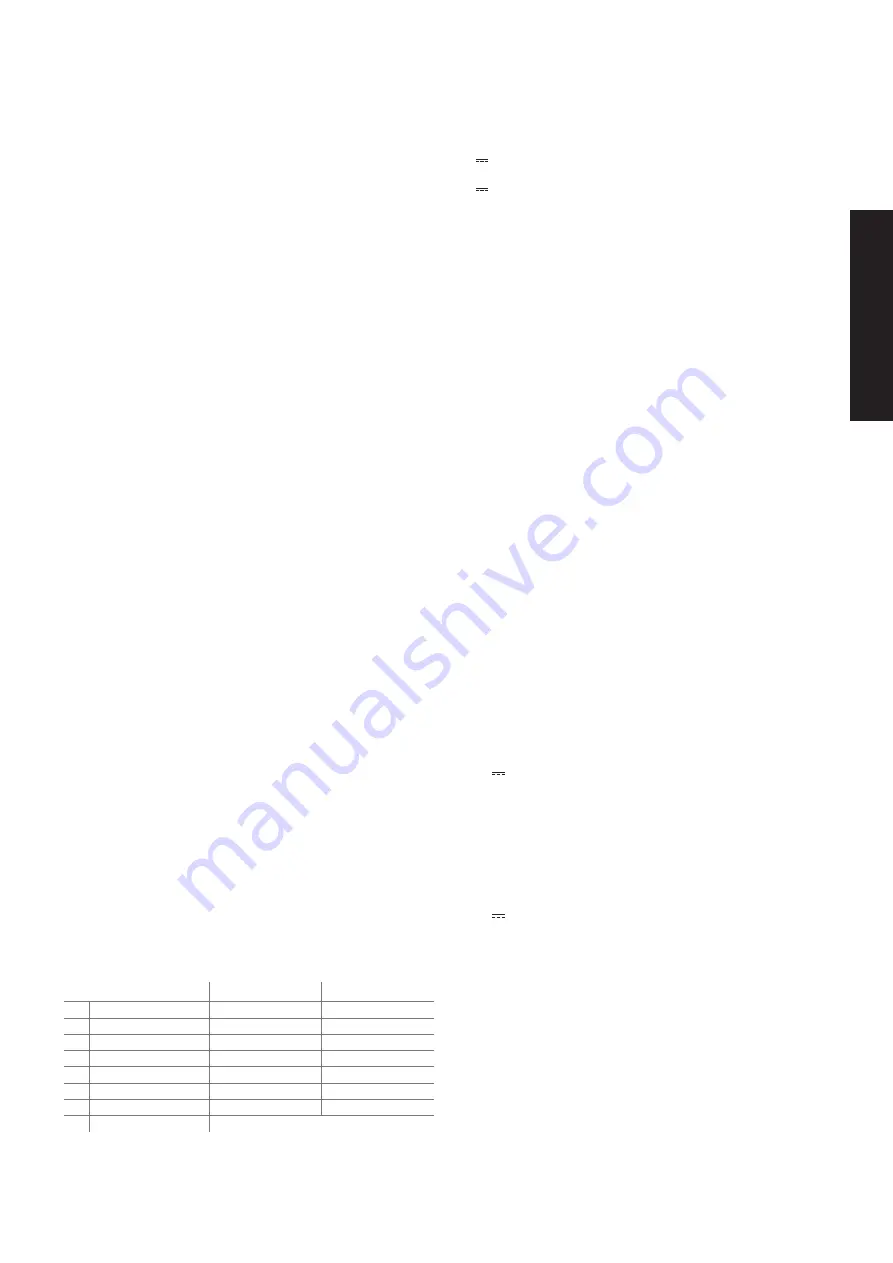
LED OFF
LED ON
L1
EL. LOCK/CLAMP
ELECTRIC LOCK.
ARM CLAMP
L2
FLASH.OUT.CNTRL.
FLASHING LIGHT
PERMANENT
L3
ALWAYS CLOSE
OFF
ON
L4
FOLLOW ME
OFF
ON
L5
PRE-FLASH
OFF
ON
L6
LED 1 OUTPUT CONTROL
ENABLED>MOTO ON
NOT ALWAYS ENABLED
L7
LED 2 OUTPUT CONTROL
FLASHING LIGHT
PERMANENT
LEV
MENU
2 FLASHES
1. ELECTRIC LOCK / ARM CLAMP SELECTION:
The control unit is factory set with the Electric lock function enabled. If you
wish to enable the Arm clamp function, proceed as follows: ensure you
have enabled Extended Menu 2 (alternate blinking 1 1 0 1 1 0 1 1 0 of
menu level no. 8) and then use the SEL key to select blinking LED L1
and press the SET key; LED L1 becomes steady on and programming will
be completed. Repeat the procedure if you wish to restore the previous
configuration.
24V 10W Electric Lock Operation:
the command is activated at each
initial opening movement for a period of 2 seconds.
24V 10W Arm Clamp Operation:
the command is activated and
remains active until the manoeuvre has been completed, with return to the
initial position.
2. 24V 25W MAX FLASHING LIGHT OUTPUT CONTROL:
The control unit is factory set with an intermittent output for connection
to a 24V Flashing light (0.5 sec ON – 0.5 sec OFF). If you wish to enable
a fixed output, proceed as follows: ensure you have enabled Extended
Menu 2 (blinking 1 1 0 1 1 0 1 0 of LED LEV) and then use the SEL key to
select blinking LED L2 and press the SET key; LED L2 becomes steady on
and programming will be completed. Repeat the procedure if you wish to
restore the previous configuration.
3. ALWAYS CLOSE:
The control unit provides the facility to set “Always Close” operation: this
function, which is programmable only if a Pause Time has already been
programmed, is activated after a power loss; if the barrier open condition
is detected, a closing movement will be started automatically, preceded
by 5 seconds of preflashing. If you wish to exclude this operating mode
proceed as follows: ensure you have enabled Extended Menu 2 (blinking
1 1 0 1 1 0 of LED LEV) and then use the SEL key to select blinking LED
L3 and press the SET key; LED L3 becomes steady on and the operation
will be completed. Repeat the procedure if you wish to restore the previous
configuration.
4. FOLLOW ME:
The control unit allows the “Follow me” function to be configured;
programmable only if a Pause Time has already been set, this function
reduces the Pause Time to 5 seconds after freeing the DS1 photocell,
meaning the barrier re-closes 5 seconds after transit of the user.
If you wish to enable this function proceed as follows: ensure you have
enabled Extended Menu 2 (blinking 1 1 0 1 1 0 of LED LEV) and then
use the SEL key to select blinking LED L4 and press the SET key; LED
L4 becomes steady on and programming will be completed. Repeat the
procedure if you wish to restore the previous configuration.
5. PREFLASHING:
The control unit is factory set with the Preflashing function disabled. If you
wish to enable the Preflashing function, proceed as follows: ensure you
have enabled Extended Menu 2 (blinking 1 1 0 1 1 0 1 0 of LED LEV) and
then use the SEL key to select blinking LED L5 and press the SET key;
LED L5 becomes steady on and programming will be completed; in this
manner the flashing light output will always switch on 3 seconds before the
barrier starts moving. Repeat the procedure if you wish to restore the initial
configuration.
6. 24V 50 W MAX. LED OUTPUT CONTROL 1:
The control unit allows selection of the barrier arm LED strip output operating
logic.
In the factory setting, the LED output is only active during movement
(including the programmed Pause Time). If you wish to enable the output in
Always On mode, proceed as follows: ensure you have enabled Extended
Menu 2 (blinking 1 1 0 1 1 0 of LED LEV) and then use the SEL key to
select blinking LED L6 and press the SET key; LED L6 becomes steady on
and the operation will be completed. Repeat the procedure if you wish to
restore the initial configuration.
7. 24V 50 W MAX. LED OUTPUT CONTROL 2:
The control unit allows selection of the barrier arm LED strip output operating
logic.
In the factory setting the LED output is of the Flashing type. If you wish to
enable the LED output in Steady On mode, proceed as follows: ensure
you have enabled Extended Menu 2 (blinking 1 1 0 1 1 0 of LED LEV) and
then use the SEL key to select blinking LED L7 and press the SET key; LED
L7 becomes steady on and the operation will be completed. Repeat the
procedure if you wish to restore the initial configuration.
RESET
If you need to reset the control unit to restore the factory settings, press the
SEL and SET keys together; this will cause all the RED indicator LEDs to
light simultaneously followed immediately by the control unit switching off.
WARNING:
restoring factory settings does not include deletion of all
previously saved Remotes and resetting of the first remote rule logic.
Summary of Contents for LIMIT 500
Page 3: ...3 COMUNELLO Copyright 2016 All rights reserved FIG 2A FIG 2B FIG 3 FIG 4 FIG 3B FIG 5...
Page 5: ...5 COMUNELLO Copyright 2016 All rights reserved FIG 7A FIG 7B FIG 8A FIG 8C FIG 8B FIG 9A...
Page 7: ...7 COMUNELLO Copyright 2016 All rights reserved FIG 13A FIG 13B FIG 14A FIG 14B...
Page 8: ...8 COMUNELLO Copyright 2016 All rights reserved FIG 16A FIG 16B FIG 15...
Page 9: ...9 COMUNELLO Copyright 2016 All rights reserved FIG 17 FIG 18A FIG 18B...
Page 10: ...10 COMUNELLO Copyright 2016 All rights reserved DEFLECTOR FIXING FIG 20A...
Page 14: ...LIMIT 800 SWING DOWN SUPPORT 45 MIN FIG A FIG C FIG B...
Page 16: ...LIMIT 600 BAR AND SKIRT FIG A FIG C FIG B 110 MIN 110 MIN 200 200...
Page 68: ...NOTES...
Page 69: ...69 COMUNELLO Copyright 2016 All rights reserved NOTES...
Page 70: ...NOTES...
Page 71: ...71 COMUNELLO Copyright 2016 All rights reserved NOTES...


