


IP HIGH SPEED DOME SERIES QUICK START GUIDE
4
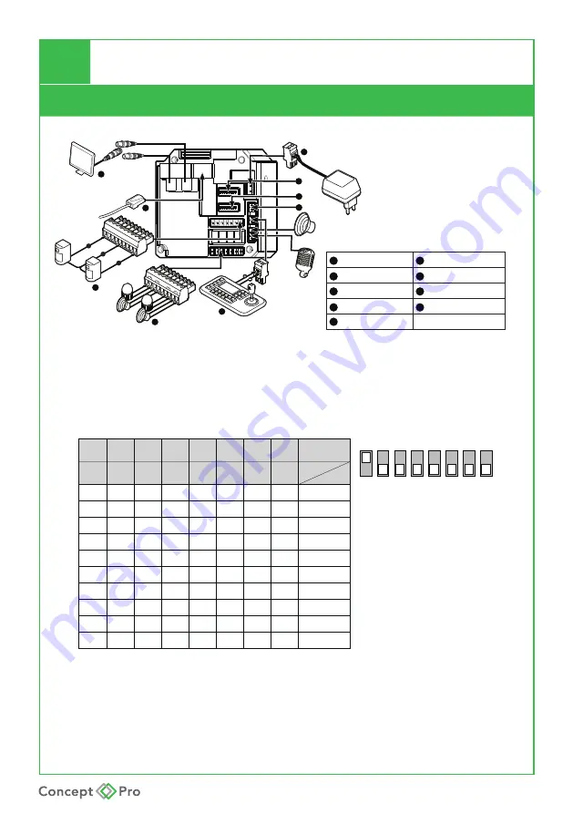
CONFIGURING THE CAMERA
Camera Connections
3
Alarm Input Terminal Block
1
BNC 1 CVBS Output
2
Network Connection
4
Alarm Output Terminal Block
5
6
DC 12V/ AC 24V Power Input
RS-485 Connector
Camera Setting Set Switch
8
Address ID Set Switch
7
9
DC12V Output
Cabling
BNC1
1
2
3
4
Speaker
Mic.
ALARM INPUT
GND
1
2
3
4
5
6
7
8
COM
In 1
In 8
OUT1
OUT2
OUT3
OUT4
5
6
8
7
9
BNC2
1. VIDEO OUTPUT
BNC1:
Analogue
(CVBS) Output.
2. Address ID Switch
1
2
3
4
5
6
7
8
ON
ON
OFF
ON
ON
ON
ON
OFF
OFF
OFF
---
OFF
ON
ON
OFF
ON
ON
OFF
ON
OFF
---
OFF
OFF
OFF
ON
ON
ON
ON
ON
OFF
---
OFF
OFF
OFF
OFF
OFF
ON
OFF
OFF
ON
---
OFF
OFF
OFF
OFF
OFF
ON
OFF
OFF
OFF
---
OFF
OFF
OFF
OFF
OFF
ON
OFF
OFF
OFF
---
OFF
OFF
OFF
OFF
OFF
ON
OFF
OFF
OFF
---
OFF
OFF
OFF
OFF
OFF
ON
OFF
OFF
OFF
1
---
2
3
5
7
4
255
6
8
-
1
1
2
3
4
5
6
7
8
2
DIP
4
8 16 32 64 128 Val ID
Factory default
switch positions
Speed dome ID is set using
standard binary notation
1
2
4
8
16
32
65 128
Note: ID 0 should not be used. Where multiple speed domes
are connected, a unique ID must be assigned to each one.


