EN
27
OPP2060
Removal
Before removal, disconnect the power cable from the wall outlet; follow the reverse steps to remove individual
parts of the unit.
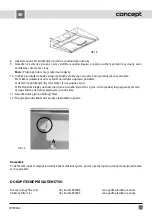
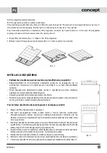
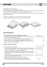
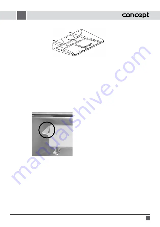
Fig. 4
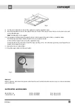
8. Fix the unit to the bottom side of the cupboard using the supplied screws.
9. Mount the backflow valve on the output hole, and connect the output hole of the fan to the hole in the wall
using a flexible pipe.
Note:
Flexible pipe is not supplied.
10. The output air will be blown through the holes in front panel of the unit in the re-circulation mode.
The following adjustment shall be made for the re-circulation mode:
a) Close all four output holes using the supplied casings.
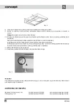
d) Operate the lever on the inner side of the top cover (Fig. 5, Pos. A) to the lower position you will open the air
output on the upper front part.
11. Mount the fat (or carbon) filter.
12. Plug the supply cable into the wall outlet.
Fig. 5
A
SUPPORTED ACCESSORIES
Metal filter 1 pc
Ord. No. 61990008
Price: See price list
Carbon filter 1 pc
Ord. No. 61990005
Price: See price list

