EN
31
OPK 5760N | OPK 5760WH | OPK 5790N
30
EN
OPK5760, OPK5790
UNIT INSTALLATION
•
Only authorized personnel can install the power connection!
• Only the customer is responsible for installation in situ. Defects caused by incorrect
installation are not covered by the warranty.
• Remove all the covering and marketing materials from the unit before the first use.
• We recommend that you let a specialized company perform the installation.
• The manufacturer bears no responsibility for damage caused to people, animals or
objects as a result of incorrect installation.
Follow the installation instructions:
1. Mark the minimum required assembly height on the wall behind the hotplate (450
mm for electric, and 550 mm for gas hotplates, Fig. 4).
2. Mark the position of the center of the hotplate with a vertical line.
3. Open the filter casing (D) and remove the fat (or carbon) filter.
4. Put the unit on the wall. You will see fixing holes through the open filter casing.
Mark their position on the wall.
5. Drill the holes.
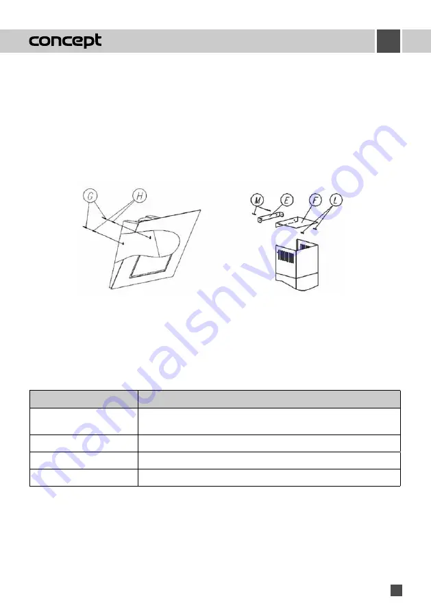
6. Mount the unit using the supplied wall plugs (G) and screws (H) at the required
height (Fig. 5).
7. For the airing mode, mount the backflow valve on the output hole, and connect the
output hole of the fan with the hole in the wall using a flexible pipe. If necessary,
use the adapter (150/120 mm).
b) Carbon filter (must be purchased)
This filter is used only in the re-circulation mode.
The filter contains active carbon that absorbs the ventilated odors. After a while the active carbon is saturated,
and loses its absorption ability. The filter can‘t be washed or otherwise cleaned.
Under normal use, the carbon filter should be replaced every 2 months. In case of more frequent frying or deep
frying, shorten the interval.
1. Open the filter casing (Fig. 1).
2. Remove the metal filter (Fig. 2), and remove the carbon filter from it.
3. Mount a new carbon filter on the metal one (Fig. 3), and put the set back.
4. Close the filter casing.
Fig. 3
Fig. 4
EN
31
OPK5760, OPK5790
Note
: Flexible pipe and diameter adapter are not supplied.
8. Mount both chimney covers to the body of the unit (B, C). Shift the upper chimney cover up to the required
height, and mark the height of the hole for the wall holder on the wall. Remove both chimney covers.
9. Drill holes at this height, and fix the wall holder of the upper chimney cover (E) to the wall plugs (M) using
screws (L). If necessary, use the upper cover (F), Fig. 6.
10. Mount and screw on the lower and upper chimney covers.
11. Mount the fat (or carbon) filter.
12.
Close the filter casing.
13. Plug the supply cable into the wall outlet.
Removal
Before removal, disconnect the power cable from wall outlet, and follow the reverse steps to remove individual
parts of the unit.
Fig. 5
Fig. 6
TROUBLESHOOTING
Problem
Cause, solution
The control does not work, or
does not work properly.
There was a voltage fl uctuation or blackout in the network. Disconnect the power
source for 10 seconds, then reconnect. The control electronics will be reset.
Low suction performance
Check and clean the metal fi lters, or replace the carbon fi lters.
"A" symbol is displayed.
Automatic fan power regulation function is ON.
"C" symbol is displayed.
Signal for check or replacement of the carbon fi lter (re-circulation).
"F" symbol is displayed.
Signal of check or cleaning of the fat fi lter (airing mode)
Summary of Contents for OPK 5760N
Page 2: ......


