32
5.6.2
Notes on electric installation
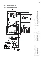
– The electric installation must be carried out according to the wiring diagram in chapter ..1 and
the applicable local regulations. All information given in the wiring diagram must be followed and
observed.
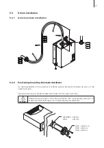
– All cables must be lead into the unit via the cable openings equipped with cable glands (e.g. option
“PG-cable gland”). The cable for the heating voltage supply must be lead into the unit from the
bottom via the cable opening equipped with the clamp strap. Fix the cable with the clamp strap.
– Make sure the cables do not scrub on any components.
– Maximum cable length and required cross section per wire must be observed.
– The supply voltages for heating and control must match the respective voltages stated in the
wiring diagram.
Heating voltage supply “Up”
Caution!
Before connecting, ensure that the mains voltage corresponds with the
heating
voltage for the unit (see mains code on the type label)
.
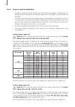
The heating voltage supply is connected to the corresponding terminals of the main contactor ac-
cording to the wiring diagram. In the supply line a
service switch “Q1”
(an all-pole disconnecting
device with a minimum contact opening of 3 mm is an essential requirement) and a
fuse group
“F1”
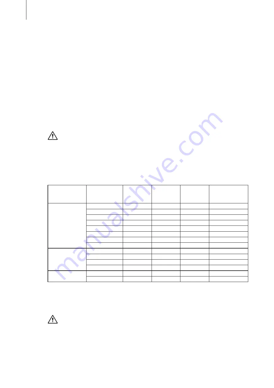
(essential requirement: fuses are to be as detailed in the following table) must be installed
(by the client).
Heating voltage
Max. steam
capacity
[kg/h]
Model
Condair CP3 D
Nominal
power
[kW]
Nominal
current
[A]
Main
fuses F3
[A]
400V3
(400V/3~/50...60Hz)
5...8
5...8
6.0
8.7
3x 10
9...12
9...12
9.0
13.0
3x 16
13...15
13...15
11.3
16.3
3x 20
16...20
16...20
15.0
21.7
3x 25
21...25
21...25
18.8
27.1
3x 35
26...30
26...30
22.5
32.5
3x 40
31...42
31...42
31.5
45.5
3x 50
43...45
43...45
33.8
48.8
3x 63
230V3
(230V/3~/50...60Hz)
5...8
5...8
6.0
15.8
3x 20
9...15
9...15
11.3
29.6
3x 40
16...21
16...21
15.8
41.4
3x 50
22...30
22...30
22.5
59.1
3x 63
230V1
(230V/1~/50...60Hz)
5
5
3.8
16.3
20
6...8
6...8
6.0
26.1
35
Note: The minimum cross section of the supply cable must comply with the local regulations.
Control voltage supply “Uc”
Caution!
Before connecting, make sure that the mains voltage corresponds with the
control
voltage of the unit (220…240 V, 50…60 Hz)
.
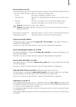
The control voltage supply is connected to the terminals L1 and N according to the wiring dia-
gram. In the supply line a
service switch “Q2”
(an all-pole disconnecting device with a minimum
contact opening of 3 mm is an essential requirement) and a
fuse “F2” (max. 10 A, slow acting,
essential requirement)
must be installed (by the client).
Note: The minimum cross section of the supply cable must comply with the local regulations.

