33
Remote indicator board H
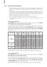
The remote operating and fault indicators must be connected to the respective potential-free relay
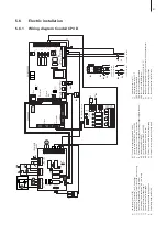
contacts of the remote indicator board according to the wiring diagram:
– “Error”:
This relay is activated if a fatal error occurs.
– “Maintenance”:
This relay is activated after the maintenance interval time has ex-
pired.
– “Steam”:
This relay is activated as soon as the CP3 D produces steam.
– “Unit on”:
This relay is activated as soon as the CP3 D is switched on.
Caution!
The maximum contact load is: 20V/1A.
Caution!
Appropriate suppressor modules are to be used for the switching of relays and
miniature contactors.
Remote temp. indication U1: Temperature signal 0...10V (0...100%) for remote temp. indication
Temperature signal U2:
Temperature signal for the control of the flap actuator
Fragrance pump M1 (230VAC)
The fragrance pump is connected to
terminals
X5-1, X5-2 and X5-3
on the steam bath board ac-
cording to the wiring diagram.
Note: The cross-section of the cable must comply with the applicable local regulations.
Steam bath lighting H3 (24VAC, max. 2x 25 W)
The steam bath lighting is connected to
terminals
X2-3 and X2-4
on the steam bath board accord-
ing to the wiring diagram
Note: The cross-section of the cable must comply with the applicable local regulations.
Steam bath fan M2 (24VAC, max. 50 W)
The steam bath fan is connected to
terminals X2-1 and X2-2
on the steam bath board according
to the wiring diagram.
Note: The cross-section of the cable must comply with the applicable local regulations.
Flap actuator M3 (24 VAC, max. 50 W)
, alternatively to the steam bath fan M2
The flap actuator is connected to
terminals X2-1 and X2-5
on the steam bath board according to
the wiring diagram. The control signal to control the flap motor is always active.
Note: The cross-section of the cable must comply with the applicable local regulations.
Temperature sensor KTY S1
The supplied temperature sensor KTY is connected to terminals
X4-1 and X4-2
according to the
wiring diagram. The steam bath board is ready for the connection of the supplied temperature sen-
sor, hence not further adjustments are required.
The temperature sensor must be installed in a appropriate location inside the steam bath (away
from the steam exit).
Please refer the separate installation instructions for proper location and connection of the tempera-
ture sensor.

