
3
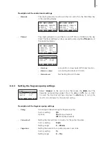
Main Menu
Mode :Manual
Aroma :Set
Info :Set
Setpoint :48°C
User :Set
Esc
Set
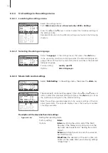
Steam Bath :Standby
CP3 D45 400V3
Temperature :34°C
Setpoint :48°C
05.05.2008 12.00.00
Start Light
Menu
Main Menu
Mode :Manual
Aroma :Set
Info :Set
Setpoint :48°C
User :Set
Esc
Set
Main Menu
Mode :Manual
Aroma :Set
Info :Set
Setpoint :48°C
User :Set
Esc
Set
Main Menu
Mode :Manual
Aroma :Set
Info :Set
Setpoint :48°C
User :Set
Esc
Set
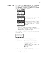
Info
ErrorHistory:Set
Unit Status :Set
Esc
Set
User Code
User Code
8808
880
8
Enter Number
Enter Number
Confirm with Set
Confirm with Set
Esc
Set
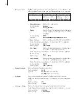
User
User
Settings :Set
Settings :Set
Modbus :Set
Modbus :Set
Maintenance :Set
Maintenance :Set
Esc
Esc
Set
Main Menu
Mode :Manual
Aroma :Set
Info :Set
Setpoint :48°C
User :Set
Esc
Set
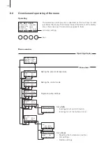
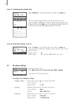
6.4
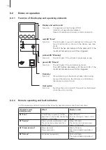
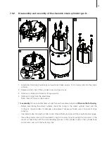
Overview and operating of the menu
The operating and display unit is operated via the four keys located
just below the display. The status fields at the bottom of the display
show the active keys the functions assigned to them.
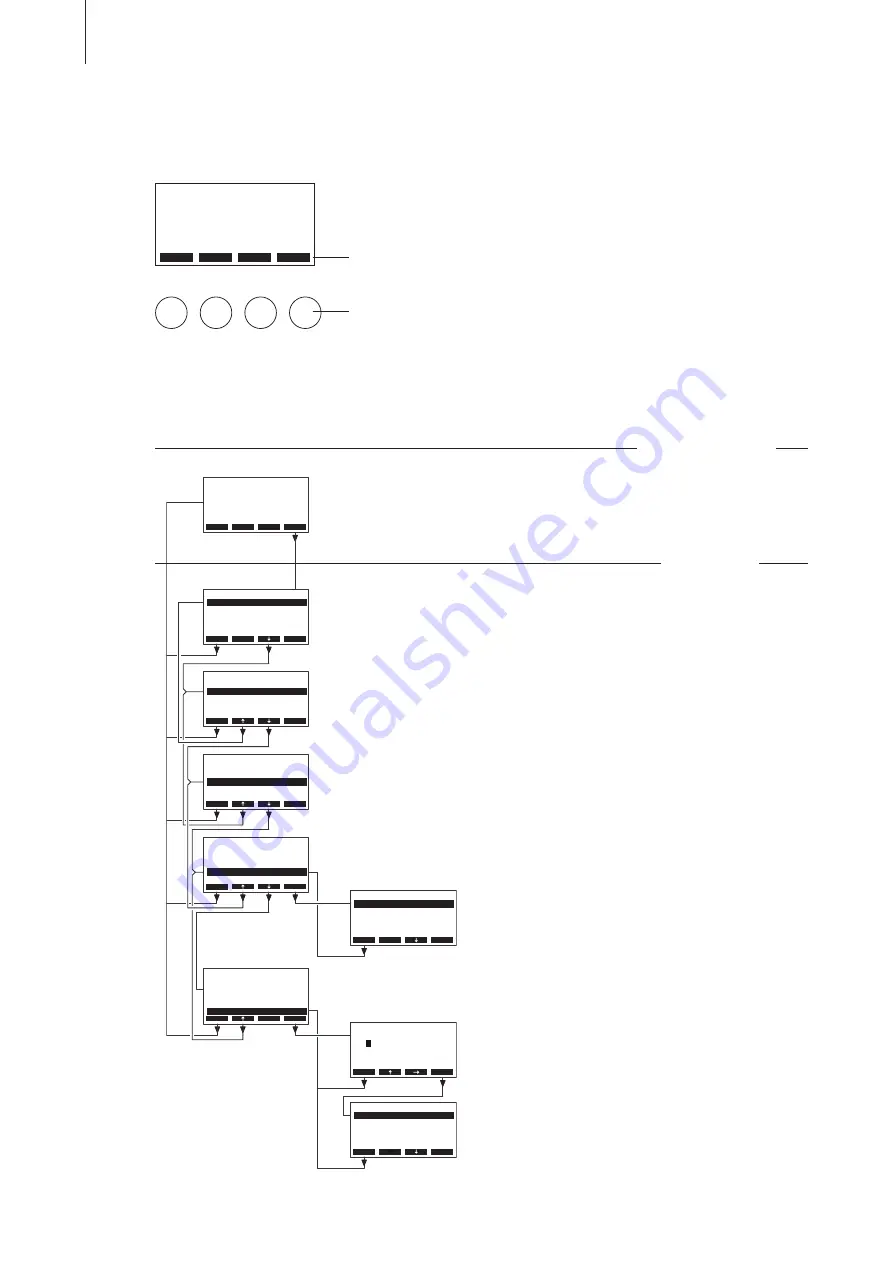
Menu overview
actual key setting
keys
Operating display
Menu level
Operating
Menu
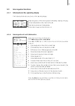
Info
– Interrogation of unit information
– Interrogation of the malfunction list
Menu
User
– Resetting the maintenance counter
– Unit settings
– Modbus settings
Steam Bath :Standby
CP3 D45 400V3
Temperature :34°C
Setpoint :48°C
05.05.2008 12.00.00
Start
Menu
Light
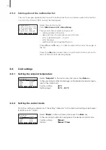
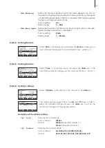
Setting the setpoint temperature
Setting the control mode
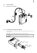
Fragrance pump settings


