background image

Nortec AirFog Installation Manual  |  

29 


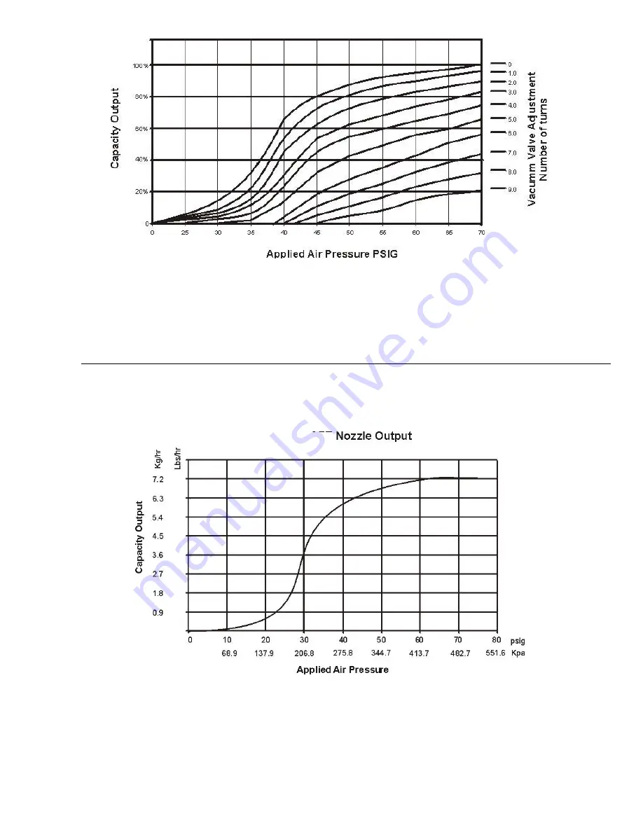
Figure 25:   Capacity Output vs. Vacuum Valve Adjustment 


Figure 26:   Nortec AFE Capacity Chart 

Summary of Contents for Nortec AIRFOG Series

Page 1: ...ation Manual Includes installation operation maintenance and troubleshooting information for your Nortec AirFog Series Atomizing humidifier 1502247 H 19 SEP 2018 Important Read and save these instruct...

Page 2: ...Ltd except to the extent required for installation or maintenance of recipient s equipment All references to the Condair name should be taken as referring to Condair Ltd Liability Notice Condair Ltd...

Page 3: ...anel 15 Electrical Wiring 18 Pilot Lines 19 Nortec AFE Self Contained Nortec AirFog Systems 19 Nortec AFE Mini Systems 21 Nortec AFE Octo Systems 21 InstallationProcedure 26 Nortec AFE Nortec MINI and...

Page 4: ......

Page 5: ...of Products The Nortec AirFog family is Condair most advanced adiabatic humidifiers There are groups of products that fall in this family applied products and packaged products The applied products gr...

Page 6: ...ng is required Since humidification is most often required when the exterior atmospheric temperature is below room temperature there is a necessity to warm the air either prior to addition of the wate...

Page 7: ...onized water types Potable water contains dissolved minerals that will precipitate out of the water in the form of dust as the water evaporates These minerals are usually not harmful to the occupants...

Page 8: ...roduced drawings Wire for the electrical connections is 18 gauge standard insulation which can carry 24 Volts AC at 1 amp This wire can be purchased from most electrical suppliers Nails screws bolts t...

Page 9: ...es is very dependent upon these obstructions Figure 1 Typical Nozzle Layout can be used as a guide for identifying the various components used with a system The supply and feed lines for the system sh...

Page 10: ...6 Nortec AirFog Installation Manual Figure 2 Multi Zone Layout Install as close to control panel as possible...

Page 11: ...odes When using Condair supplied saddle clamps the maximum line size for supplying to nozzles is 11 16 O D If saddle clamps by others are used please size fittings to match the pipe Cleaning Manual va...

Page 12: ...ion Primary Water Pressure Control Section Figure 3 Water and Air Line Pressure Control Mounting Holes For 1 4 Lag Bolts Lag Bolts Supplied By Others Saddle Clamp Polytube Nortec AFE Nozzle Saddle Cla...

Page 13: ...ing MUST be cut square using a knife or plastic tube cutter rather than pliers To connect the tube to the nozzle simply push the tubing into the nozzle fitting until it reaches the bottom Gentle pulli...

Page 14: ...ng Seal Locking Ring 1 4 Tubing Locking Fingers O Ring Seal NPT Threads 1 4 Tubing TubingMUSTbe cut PERPENDICULAR to ensure proper seal Use sharp knife not wire cutters or pliers Figure 6 Quick Releas...

Page 15: ...regulator is used as the first stage of water pressure reduction The water regulator reduces the supply water pressure to a range between 5 and 10 psig This is set manually at time of installation Pl...

Page 16: ...feed the output air feed to the nozzles and to gauge port used to feed pilot signal to the water regulator There are no manual adjustments required Install the pilot air regulator on the feed line bef...

Page 17: ...ive pressure pulls the VV diaphragm down opening the water valve Air Compressor As the pressurised water enters the VV chamber it pushes up on the diaphram closing the water valve During normal operat...

Page 18: ...tec AirFog Installation Manual Outlet Port Pilot Operated Air Regulator Inlet Port Pilot Line from Control Panel Figure 10 Pilot Air Regulator Figure 11 Pilot Air Regulator Installation Feed Line to N...

Page 19: ...h is provided by the Condair supplied step down transformer 120 VAC to 24 VAC The transformer plugs into any standard 120 VAC outlet that must be located within 6 six feet of the control panel Power i...

Page 20: ...s Union Air Regulator 1 2 NPT Brass Union Filter optional Figure 12 Primary Air Pressure Control Section Shut Off Valve 1 2 NPT Brass Union Pressure Gauge 0 100 PSIG 1 2 FNPT Brass Y Type Strainer 1 2...

Page 21: ...Pilot Outlet Pilot Inlet Main Air Lock Pressure Regulator Yellow Light Humidifying Green Light on off On Off Switch Control Wiring Input Figure 14 Control Panel 24 VAC Modulation Input On Off Controls...

Page 22: ...control panel requires an input pneumatic air control supply which is usually tapped off the main air supply line upstream of the pilot air regulator The control panel has two pneumatic fittings loca...

Page 23: ...abatic cooling may be uncomfortable to people occupying workstations directly beneath the Nortec MINI systems The Nortec MINI nozzles must be a minimum of 6 feet above the floor and 36 below the ceili...

Page 24: ...20 Nortec AirFog Installation Manual Figure 17 Control Panel Figure 18 Nortec AirFog Mini Connections 3 ft 1 m minimum 15 ft 4 5 m clearance each nozzle 6 ft 1 8 m minimum...

Page 25: ...designed to be suspended from the ceiling by either a threaded rod or chains Nortec Octos with nozzles on only one side may also be mounted on a wall or pillar single sided configurations Prior to mo...

Page 26: ...22 Nortec AirFog Installation Manual Figure 19 Nortec Octo Layout with Interfaces Figure 20 Nortec Octo Spray Pattern...

Page 27: ...connection Simply cut the tubing square and push one end into the fitting Route the line back to control panel location If multiple Nortec Octo units are to be controlled from a single control panel...

Page 28: ...eve by a min 0 125 3mm Plastic Tube Forcopper tubingreplace plastic sleeve with thesupplied brass sleeve LockingNut BulkheadUnionon plumbing side Pilotinconnection 1 4 quick connect Water connection 3...

Page 29: ...Nortec AirFog Installation Manual 25 Figure 23 Four Nortec Octo Units with a Single Control Panel Figure 24 Nortec AFE Octo Nozzle Spray Pattern...

Page 30: ...the ON position The handle should be in line with the pipe as opposed to 90 degrees to it The control panel switch is turned to the ON position Adjust the air pressure regulator in the control panel t...

Page 31: ...lve Adjustment for more information Self Cleaning Cycle Adjustment The Nortec AFE Nortec MINI and Nortec Octo Systems all feature an automatic self cleaning mechanism that prevents mineral build up in...

Page 32: ...less than 15 minutes are not recommended Setting the System for Normal Operation Once the start up and adjustment and configuration procedures have been completed the unit is ready to operate normally...

Page 33: ...Nortec AirFog Installation Manual 29 Figure 25 Capacity Output vs Vacuum Valve Adjustment Figure 26 Nortec AFE Capacity Chart...

Page 34: ...air pressure control system Turn the system off at the control panel Turn the air compressor off For long periods weeks or longer of system down time it is recommended that pressurized air is used to...

Page 35: ...ed with each kit Seasonal Maintenance In most cases there is a humidification season but if this is not the case it is recommended that the following actions be conducted once a year A detailed visual...

Page 36: ...til the system is turned on and a pilot signal of 15 psig or greater is applied Adjust vacuum valve thumb wheel to zero force spring backed off While system in operating visually watch the spray patte...

Page 37: ...required amount of vacuum needed to operate the vacuum valve Since the nozzles can only generate a fixed amount of vacuum negative pressure the flow rate of water is reduced which causes a finer spray...

Page 38: ...ontrolled air pressure Repair Stuck Closed Or Open Unable to adjust pressure Disassemble and clean Pilot Water Regulator Damaged Diaphragm Loss in water pressure No water pressure Uncontrolled water p...

Page 39: ...tubes The lead time to obtain replacement parts or repair kits is considered an acceptable risk Other owners decide that this risk is too high and choose to maintain spare parts and repair kits in hou...

Page 40: ...36 Nortec AirFog Installation Manual Nortec Octo Exploded View Spare Parts Figure 27 Nortec Octo Exploded View...

Page 41: ...64 3 Way Solenoid Valve 24 VAC Replacement Kit 0 0 0 1 1 1 1 1 1 4 1603020 On Off Switch Assembly 0 0 0 1 1 1 1 1 1 5 1603021 Pilot Lamp Assembly 0 0 0 1 1 1 1 1 1 6 1603001 Air Regulator Panel Mount...

Page 42: ...e Parts Figure 28 Nortec AFE Nozzle Exploded View Item Part Description Qty 1 1603120 Nortec AFE Nozzle Repair Kit 1a O Ring Seal 2 1b Flat Washer 2 1c Retaining Clip SST 2 1d O Ring Valve Seat 1 1e P...

Page 43: ...Nortec AirFog Installation Manual 39 Vacuum Valve Exploded View Spare Parts Figure 29 Vacuum Valve Exploded View...

Page 44: ...O Ring 1 1 1 2 1603002 Panel Mount Water Reg 1 4 P 1 1 1 1603119 Repair Kit for 1603002 Water Regulator 1 1 1 1603114 Panel Mount Water Reg 1 4 P SST for DI 1 1 1 3 1603008 Pressure Gauge 1 1 2 1 8 CB...

Page 45: ...Only 0 1 3 1506260 E P Converter Module Modulating Control Panel Only 0 1 4 1603050 Repeat Cycle Timer 1 1 5 1603200 Pressure Gauge Panel MTG Bars 1 1 6 1493096 Lamp Green Indicator 1 1 7 1453001 Swit...

Page 46: ......

Page 47: ...rther warranty must be in writing signed by an officer of THE COMPANY THE COMPANY s parts or materials that are considered consumables including but not limited to cylinders filters nozzles membranes...

Page 48: ...U S A 2700 90th St Sturtevant WI 53177 835 Commerce Park Dr Ogdensburg NY 13669 2209 CANADA 2740 Fenton Road Ottawa Ontario K1T 3T7 TEL 1 866 667 8321 EMAIL na info condair com WEBSITE www condair com...

Reviews: