Operating Instructions (GB)
900 191 - V1.0
_________________________________________________________________________________
Page 8
6.2
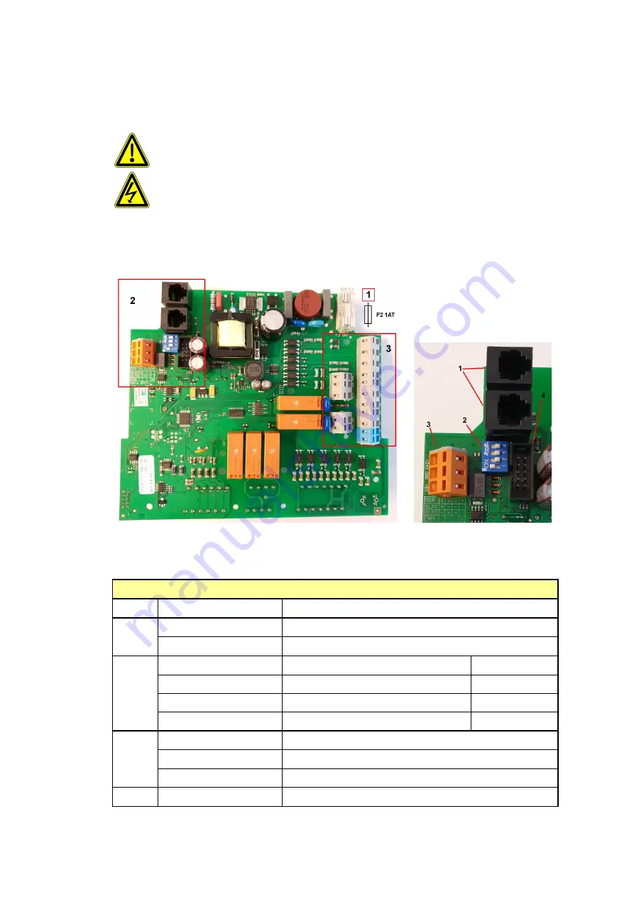
Back of base circuit board (GLP)
In case of defect, it may be necessary to replace the base circuit board.
This requires function-critical components to be dismantled. Improper handling can
cause damage, which is not covered by the warranty. The board should be
replaced by the manufacturer if possible.
Only trained personnel is allowed to undertake the installation.
Section 1 shows the internal fuse F2 of the control electronics 1AT
.
Fig. Back of base circuit board
Fig. Image section 2
Description of image section 2
Item
Designation
Explanation
1
RJ 12 socket
Connection for control board (CPU) cable
RJ 12 socket
Reserve
2
DIP switch 1
Base circuit board 1 (GLP1)
ON
DIP switch 2
Reserve
OFF
DIP switch 3
Reserve
OFF
DIP switch 4
Set terminal resistance
ON
3
+24V
Voltage 24 VDC 50 mA
GND
Reference point for voltage o 24 VDC / + 5 VDC
+5V
Voltage 5 VDC
(do not use)
4
10-pin box header
Connection for battery module cable


