background image

user manual

CROSS 

LINE LASER

EN

user manual

CROSS 

LINE LASER

EN

XLiner Pento 360/360G

XLiner Pento 360/360G

14

15

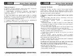
Check of vertical line

Use a plumb bob as a reference of a vertical line. Place the instrument 

at distance of 1,5m from the plumb bob. 

1. Unlock the compensator, switch on the vertical laser line and align it 

with the low point of plumb bob. 

2. If deviation between the laser line and the plumb bob line exceeds 

±0.2 mm per 1m of the plumb bob length (for a 2.5m plumb bob 

deviation shouldn’t exceed 0.5 mm) please contact service center. 

3. Turn the instrument by 180° and align the vertical laser line with the 

low point of plumb bob once again.

1,5m

CARE AND MAINTENANCE

Attention!

 The laser level is an accurate optical mechanic device 

and requires careful handling. Check the accuracy before using. 

Maintenance of the following recommendations will extend the life 

of the device:

- Keep the laser level, spare parts and accessories out of the reach of 

children and unauthorized people.

- Transport the laser level with locked compensator only.

- Protect the device from shock, falls, and strong vibrations; do not 

allow moisture, construction dust, and foreign objects to get inside 

the laser level.

- In case moisture gets inside the laser level, first of all, remove the 

battery, and then contact the service center.

- Do not store or use the laser level for a long time in high humidity 

conditions.

- Arrange the accuracy check of the laser level occasionally (see the 

paragraph «Accuracy check»).

- Clean the laser level with a soft damp cloth. Do not use harsh 

chemicals, cleaning solvents or detergents.

- Wipe the laser aperture with a soft, lint-free cloth with isopropyl 

alcohol.

Failure to comply with the following rules may result in leakage of 

the electrolyte from the batteries and damage the laser level:

- Remove the battery from the laser level if it is not used for a long 

time.

- Do not leave discharged battery in the device.

- Do not heat the battery.

Summary of Contents for 1-2-158

Page 1: ......

Page 2: ...18 BESTIMMUNGSGEMAESSER GEBRAUCH 19 LIEFERUMFANG 21 TECHNISCHE DATEN 22 VOR INBETRIEBNAHME 23 BETRIEB 23 GENAUIGKEITSUEBERPRUEFUNG 25 PFLEGE 29 ENTSORGUNG 29 GARANTIE 30 WARTUNG UND REPARATUR 31 RU 3...

Page 3: ...unauthorized people Do not disassemble or repair the product yourself Entrust product repair to qualified personnel and use original spare parts only Do not use the product in explosive environment c...

Page 4: ...ting on a tripod 5 Thread 5 8 for mounting on a tripod 6 Switch bar 7 Hole for mounting on a screw nail 1 3 4 5 6 Control panel 1 Switch on off the laser level laser planes 2 Switch on off pulse mode...

Page 5: ...e battery in the battery compartment observing the polarity Use the battery included in the delivery package only If the power indicator on the control panel starts flashing red the battery must be ch...

Page 6: ...ll The layout should be made along the axis of the laser line For maximum accuracy use the middle portion of the laser line It should be noted that the shape of the laser line on the object s surface...

Page 7: ...osite wall B and set it in such a way so that the point where laser lines intersect each other would be on the same level with point B2 see Fig C C 4 Turn the instrument by 180 direct the instrument t...

Page 8: ...life of the device Keep the laser level spare parts and accessories out of the reach of children and unauthorized people Transport the laser level with locked compensator only Protect the device from...

Page 9: ...r see the original supporting document 3 The Warranty doesn t cover defects resulting from wear and tear or improper use malfunction of the product caused by failure to observe the instructions of thi...

Page 10: ...artung duerfen nur durch Fachpersonal mit Qualifikation erfolgen das originale Ersatzkomponenten einsetzt Kinder duerfen aus Sicherheitsgruenden das Geraet nur unter Aufsicht benutzen Verwenden Sie da...

Page 11: ...5 8 Stativaufnahme 6 Pendelsperre 7 Befestigungsmoeglichkeit fuer Nagel oder Schraube Bedienfeld 1 Ein Ausschalter f r Kreuzlinienlaser Laserstrahlen 2 Taste zum Ein Abschalten des Empfaengerbetriebs...

Page 12: ...Sie die Batterie im Batteriefach unter Beachtung der Polarit t Verwenden Sie nur die im Lieferumfang enthaltene Batterie Wenn die Betriebsanzeige auf dem Bedienfeld rot blinkt muss die Batterie gelad...

Page 13: ...iebsabstand zunimmt Das layout sollte entlang der Achse der Laserlinie erfolgen Verwenden Sie f r maximale Genauigkeit den mittleren Teil der Laserlinie Es sollte beachtet werden dass die Form der Las...

Page 14: ...raet an die Wand B und richten Sie den Laser so dass das Laserkreuz auf der gleichen Ebene mit dem Punkt B2 ist Siehe Abb C C 4 Drehen Sie das Geraet um 180 und markieren Sie den Kreuz an der Wand A m...

Page 15: ...Genauigkeit des Ger tes nachdem es fallen gelassen wurde oder anderen mechanischen Belastungen ausgesetzt war Schalten Sie das Geraet nach der Verwendung wieder ab da andere Personen oder Tiere von d...

Page 16: ...mbH behaelt sich das Recht vor nach eigener Entscheidung das Geraet zu reparieren oder zu ersetzen 5 Andere Ansprueche als die oben genannten werden nicht ueber die Garantie abgedeckt 6 Nach Garantiel...

Page 17: ...RU RU XLiner Pento 360 360G XLiner Pento 360 360G 32 33 XLiner Pento 360 360G CONDTROL 2 1 635 515 IEC 60825 1 2007 03 10 XLiner Pento 360 360G CONDTROL 2 3 5...

Page 18: ...RU RU XLiner Pento 360 360G XLiner Pento 360 360G 34 35 1 2 3 4 1 4 5 5 8 6 7 1 2 3 4 5 1 7 4 2600 2 1 1 C 1 1 3 4 5 6 2 7 1 2 3 5 4...

Page 19: ...ento 360 360G XLiner Pento 360 360G 36 37 XLiner Pento 360 XLiner Pento 360G 40 100 60 100 0 2 3 5 18 8 10 C 50 C 20 C 70 C 90 IP54 1 4 5 8 II 635 1 II 515 1 7 4 2600 155x85x132 0 63 0 73 7 4 2600 1 2...

Page 20: ...RU RU XLiner Pento 360 360G XLiner Pento 360 360G 38 39 2 OFF 2 2 5 2 Bluetooth Bluetooth Bluetooth XLiner Remote Bluetooth 2 5 1 1 A 5...

Page 21: ...RU RU XLiner Pento 360 360G XLiner Pento 360 360G 40 41 2 180 2 B 3 B2 C 4 180 1 A3 D D 5 e d 1 3 D 2...

Page 22: ...RU RU XLiner Pento 360 360G XLiner Pento 360 360G 42 43 1 5 1 2 0 2 1 2 5 0 5 3 180 c 1 5...

Page 23: ...RU RU XLiner Pento 360 360G XLiner Pento 360 360G 44 45 24 36 www condtrol ru 2002 96 2006 66...

Page 24: ...e nale y demontowa ani naprawia produktu samodzielnie Konserwacj i naprawy powinny by powierzane wy cznie Promieniowanie laserowe Nie kierowa wi zki w oczy Laser klasy 2 1 MW 635 515 nm IEC 60825 1 20...

Page 25: ...mpulsowego 3 Wska nik zasilania 4 Wska nik blokady kompensatora 5 Wska nik trybu impulsowego WYPOSA ENIE Niwelator laserowy 1 szt kumulator 7 4 2600 m h litowo jonowy 2 szt adowarka 1 szt Instrukcja u...

Page 26: ...mulator w komorze baterii PRACA Z NARZ DZIEM Zamontuj instrument na solidnej stabilnej powierzchni lub statywie Wybra tryb pracy za pomoc suwaka blokady 1 Tryb automatycznej kompensacji Przesun suwak...

Page 27: ...naczy punkt B1 A 5m 2 Tryb tworzenia p aszczyzn pochylonych Przesun suwak blokady w po o enie OFF W czy narz dzie d ugim naci ni ciem klawisza w ci gu 2 sekund Poprzez d ugie nast puj ce po sobie naci...

Page 28: ...przeci cia linii laserowych na cianie za pomoc znaku A3 patrz rys D D 5 Zmierzy odleg o cimi dzy znakami A1 i A3 patrz rys D Je li ta odleg o przekracza 2 mm skontaktowa si z centrum serwisowym 2 Obr...

Page 29: ...rawdza urz dzenie pod wzgl dem dok adno ci patrz rozdzia Kontrola dok adno ci Urz dzenie nale y czy ci mi kk wilgotn ciereczk Nie nale y u ywa agresywnych chemikali w rozpuszczalnik w czyszcz cych ani...

Page 30: ...OL GmbH Wasserburger Strasse 9 84427 Sankt Wolfgang Germany Nie wyrzuca urz dzenia do odpad w komunalnych Zgodnie z dyrektyw europejsk 2002 96 WE zu yte narz dzia pomiarowe i ich cz ci sk adowe musz b...

Page 31: ......

Reviews: