4 4
In st ru c t io n m an u al
C o n e r g y IP G s t r in g in v e r t e r s e r ie s
6 In s t a lla t io n a n d c o m m is s io n in g
E
N
G
L
IS
H
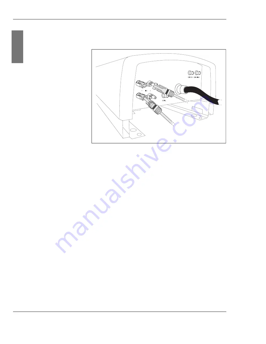
12.Place the connector sockets and connector plugs onto the
plugs and sockets of the string inverter.
Fig. 6-12: Connecting the solar system
Junction box
If you have chosen to combine the Conergy IPG series
inverter with the Conergy IPG easyconnect generator
junction box, you will save valuable installation time. The
solar system is connected to the Conergy IPG easyconnect
and from there to the inverter. Connection cables for this
purpose are provided behind the generator junction box. All
you need to do is draw the cables out to the required length
(max. 5 m) and connect them to the connector socket or
connector plug of the inverter. Please see the Conergy IPG
easyconnect generator junction box instruction manual for
further information.
6.6
Connecting the Conergy SunReader:
If you have chosen to use the Internet-based Conergy
SunReader monitoring system, connect the Conergy IPG
series string inverter to the Conergy data logger. Each
Conergy IPG series string inverter has a
CAN In
connection
(see Fig. 6-1, page 35, pos.
(1)
). The CAN cable is included
in delivery of the Conergy SunReader. Please see the
Conergy SunReader instruction manual for further
information.


