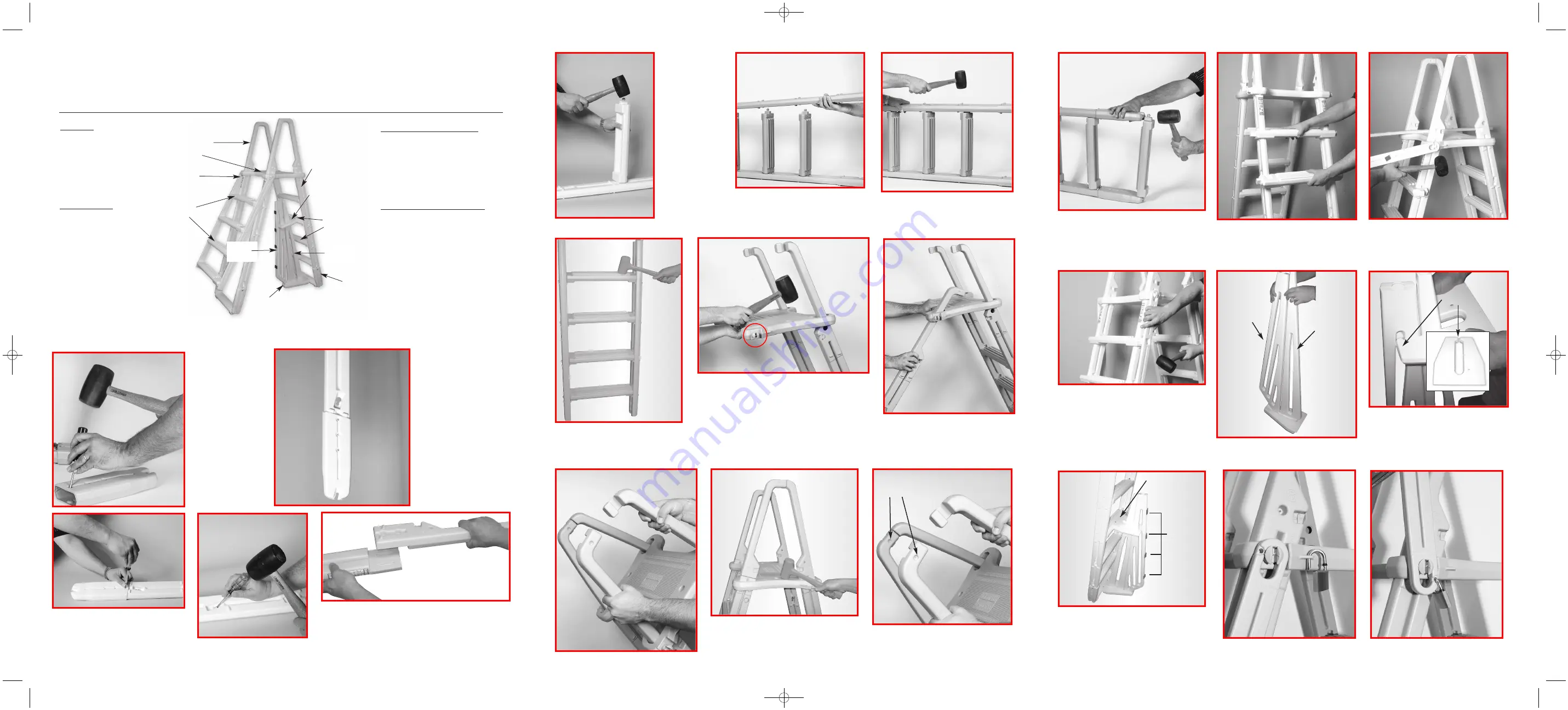
Platform
Handrails
Tread
Connector
Swing Up
Tread
Upper Brace
Ladder Leg
Standard
Tread
Extension
Boot
Lower Base
Large
Barrier
Small
Barrier
Hardware Pack
4 - 1/4 - 20 x 2" Bolt
4 - 1/4 - 20 Acorn Nut
2 - #10 x 1-1/4" Screw
2 - 1/4 - 20 x 2-1/4" Bolt
2 - 1/4” Flat Washer
10 - 1/4 - 20 Hex Nut
4 - Plug
1 - Padlock
8 - 1/4 - 20 x 1" Bolt
Tools Needed for Assembly
* - Hammer or mallet
* - Phillips Screwdriver
* - Adjustable wrench
* - Liquid soap or lubricant
* - Battery operated drill motor
* - 5/16” Drill bit
Barrier Parts List (if included)
(Included in Hardware Pack)
4 -
#10 x 1-1/4” screws
1 - Strip of 4 Foam Pads
1 - Large Barrier Section
1 - Small Barrier Section
1 - Upper Brace
1 - Lower Base
Model #7100X
A-FRAME LADDER
Adjustable to fit 48” to 54” LADDER MUST BE ATTACHED TO POOL FRAME...
DO NOT USE WITH INFLATABLE POOLS
ASSEMBLY INSTRUCTIONS - PLEASE READ BEFORE ATTEMPTING ASSEMBLY
Parts List
4 - Ladder Legs
2 - Tread Connectors
4 - “Swing Up” Treads
6 - Standard Treads
4 - Extension Boots
1 - Platform
4 - Handrails
If missing parts call - Toll free U.S. - 800-635-3213 or www.conferladders.com
*NOTE: If you are using this ladder on a 48” pool you will not use the extension boots. Proceed to #4.
13.
14.
Tap the platform down until fully seated on
the lugs as shown.
Connect the top of the handrails together.
Using a #10 x 1-1/4” screw fasten the
upper ends of the handrails together
as shown. Repeat for opposite side.
Position the tread connector as shown,
with the padlock hole facing upward, and
tap it over the round knob. Repeat for the
opposite tread connector.
16.
17.
Position the four “swing up” treads
onto the ladder legs as shown.
If the round
plastic inserts,
on the sides of
the extension
boots, are still
in place,
remove them
with a phillips
head screw-
driver as
shown.
Slip the four extension
boots over the ends of
the ladders legs. They
will need to be all the
way on for most 52” tall
pools and backed off
one hole for 54” pools.
Depending upon
ground levels outside
the pool, and sand
levels under the liner
inside the pool, a final
adjustment may need
to be made after the
ladder is put into place.
3.
4.
6.
7.
Place the second ladder leg with
the keyhole inserts removed over
the treads and tap down.
9.
With the ladder standing up, tap the
treads all the way down until seated
in the keyhole slots
12.
3
2
4
8.
Tap the ladder leg down onto the ends
of the treads.
1.
2.
Using four 1/4-20 x 2” long bolts and
four acorn nuts fasten the extension
boots to the ladder legs
Using a Phillips screwdriver, knock
out all four of the keyhole slot
inserts from two of the ladder legs.
Push the end of
one of the
standard treads
into the uppermost
keyhole slot. Make
sure that the tread
and the ladder leg
are positioned as
shown in the pho-
tograph to the left.
It may be
necessary to tap
the tread into the
slot with a mallet.
Repeat for three
additional treads.
15.
Attach the two remaining standard
treads to the extension boots (or directly
to the ends of the ladder legs if installing
on a 48” tall pool).
Snap Small and Large Barrier Sections
into slots on Lower Base as shown.
Separate Barrier sections at the top
slightly and position Upper Brace over
Small Barrier Section. Next, spread the
“fingers” on the Upper Brace and slide
into position on the Large Barrier Section.
Fingers
19.
20.
21.
Place the Base and Brace into position, centered,
on the bottom and fourth treads of the ladder.
Install the four (4) #10 x 1-1/4" screws (included in
hardware pack) on a slight angle, first in the
Upper brace, then in the Lower Base. Install the
self-adhering foam strips to the Large Barrier
Section as shown in diagram.
Foam
Pads
“Swing” up portion of ladder shown
in “down” position and the padlock
in the “holding” area.
Swing up portion of ladder shown in
“up” position, secured with padlock.
Insert screws here
22.
23.
Screws
Large
Barrier
Small
Barrier
If Ladder
did not include Barrier, skip steps 21 through 23. Continue to step 24.
Place handrail over the flat area located on top of
ladder leg. Insert one of the 1/4 - 20 x 1" bolts
through the ladder leg into the handrail. Place one
1/4 - 20 hex nut into the recessed area on the
handrail and tighten using a Phillips screwdriver.
Install the second bolt and nut. Repeat to assemble
all four ladder leg/handrail assemblies.
10.
11.
Making sure that the “swing-up” side of the
platform is facing away from the “inside” ladder
section, as shown, slip the openings of the
platform over the upper ends of the ladder legs.
Using a mallet or hammer tap the platform
down until it is fully seated onto the “nubs” of
the ladder legs. Liquid soap or lubricant will
help the parts slide together.
Slip the other two ladder legs
through the openings of the platform
until they engage the other ladder
legs as shown in next photo.
5.
18.
Lay ladder on its side, put a little liquid
soap onto the square ends of the treads.
Next place the tread connector onto the
ends of the treads and strike hard with a
rubber mallet to seat tread connector
onto the treads. Flip ladder over and
repeat for second tread connector.
Confer 7100X-9/13:Confer 7100_2_07 10/7/13 11:57 AM Page 4


