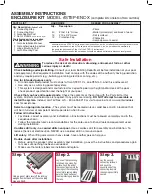
With a cordless drill fasten the
connector kit to the handrail
posts using (16) #10 x 1-1/4”
screws (eight per side) at
each of the pre-marked
locations.
Step 5.
Step 6.
3
Secure the
connecting step by fully
inserting the locking wedges
saved from step #1 between the
side panel and the top surface of both
ends of each step. Tap in place with a hammer.
With one of the assembled step
units at the desired location inside
the pool, and the second unit
placed outside the pool, slide the
assembled connector kit down
over the upper handrail posts until
it is resting on the pool top seat.
Attach the
handrails to
the inside
unit only as
described in
step 11 of the
STEP-1X
instructions.
Slide the gate
adapter posts
down over
the short
handrail posts
of the outside
unit until they
bottom out.
Step 4.
Step 4.
WARNING! Verify that your
chosen step system location
is level, has a solid base, and
will be in full view of competent
adult supervision when in use.
WARNING! Do not stand on the top steps of
the unit until fully assembled as it may tip.
WARNING! Pool step will be
heavy. Have additional help. Do
not attempt to place the step by
yourself.
WARNING! Using a corded drill near
pool may result in electrocution.
Step 7.
Step 8.
Step 8.
Insert the ends of
the notched
handrails into the
open ends of the
posts on the
outside unit.
Fasten in place
using four #10 x
1-1/4” screws.
Step 9.
Step 9.
Align one of the triple pickets into the notches of the handrail at the top of the unit. Fasten the
pickets in place at the top of the pickets using the #10 x 3/4” screws. Continue placing and
fastening the double pickets and then the single picket. Repeat for the opposite handrail. Cover
the ends of the screws with the protective caps.
Step 10.
Fasten the
pickets to the
step unit at the
pre-marked loca-
tions with
twelve #10 1-1/4”
screws.
Also, secure
the gate
adapter posts
and upper
handrail posts
in place with
#10 x 1-1/4”
screws at the
pre-marked
locations.
Step 11.
Gate
installation: see
instructions
enclosed with
gate. There are
two differences
for this
installation. For
this installation
the gate posts
slide over the
adapter posts
as shown here.
And; You must
also fasten the
lowest corner of
that flange to
the step unit as
shown (see photo at far right). NOTE: the
hinge post must be on your right-hand side
(as you are looking up the steps).
Step 12.
IMPORTANT: Fasten the
lowest corner of each flange to
the step as shown below.


