Copyright
©
2020
congatec
AG
ICWLm12
50/62
8
GND
Ground reference
9
SMB0_CLK
3.3 V
SMBus clock output
10
+ 3.3 V
2
+3.3 V standby power (deep) output with 500 mA
Note
1.
Recommended for I2C devices.
2.
Recommended for SM bus devices.
Connector Type
X43: 8-pin, 1.25 mm pitch picoblade header (Molex 0533981071)
X52: 10-pin, 1.25 mm pitch picoblade header (Molex 530471010)
Possible Mating Connector: Molex 510211000
5.11
Front Panel Header
The conga-IC370 provides pin header X47 for front panel features such as reset and power buttons, power state bidirectional LED and SATA
LED. Pins 2 and 4 indicate the conga-IC370 power states. For LED status description, see section 5.1.3 “Power Status LEDs”.
Table 43 X47 Pinout Description
Pin Signal
Description
1
SATA activity LED (anode) driven by 5 V with 470 ohm resistor
2
Power LED (anode for main color, cathode for alternate color) driven by 3.3 V with 330 ohm resistor
3
HDD_LED-
SATA activity LED (cathode) driven by 5 V with 470 ohm resistor
4
FP_LED-
Power LED (cathode for main color, anode for alternate color) driven by 3.3 V with 330 ohm resistor
5
GND
Ground
6
PWRBTN#
Power Button (Note: for proper detection, assert a pulse width of at least 16 ms)
7
SYS_RST#
Reset Button (Note: for proper detection, assert a pulse width of at least 16 ms)
8
GND
Ground
9
+5 V
+5 V runtime power supply (500 mA power budget)
10
KEY
No pin
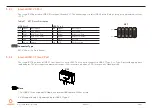
Connector Type
X47: 2.54 mm,10-pin header (without pin 10)
X47
Pin 9
Pin 1
No Pin
Pin 2


