background image

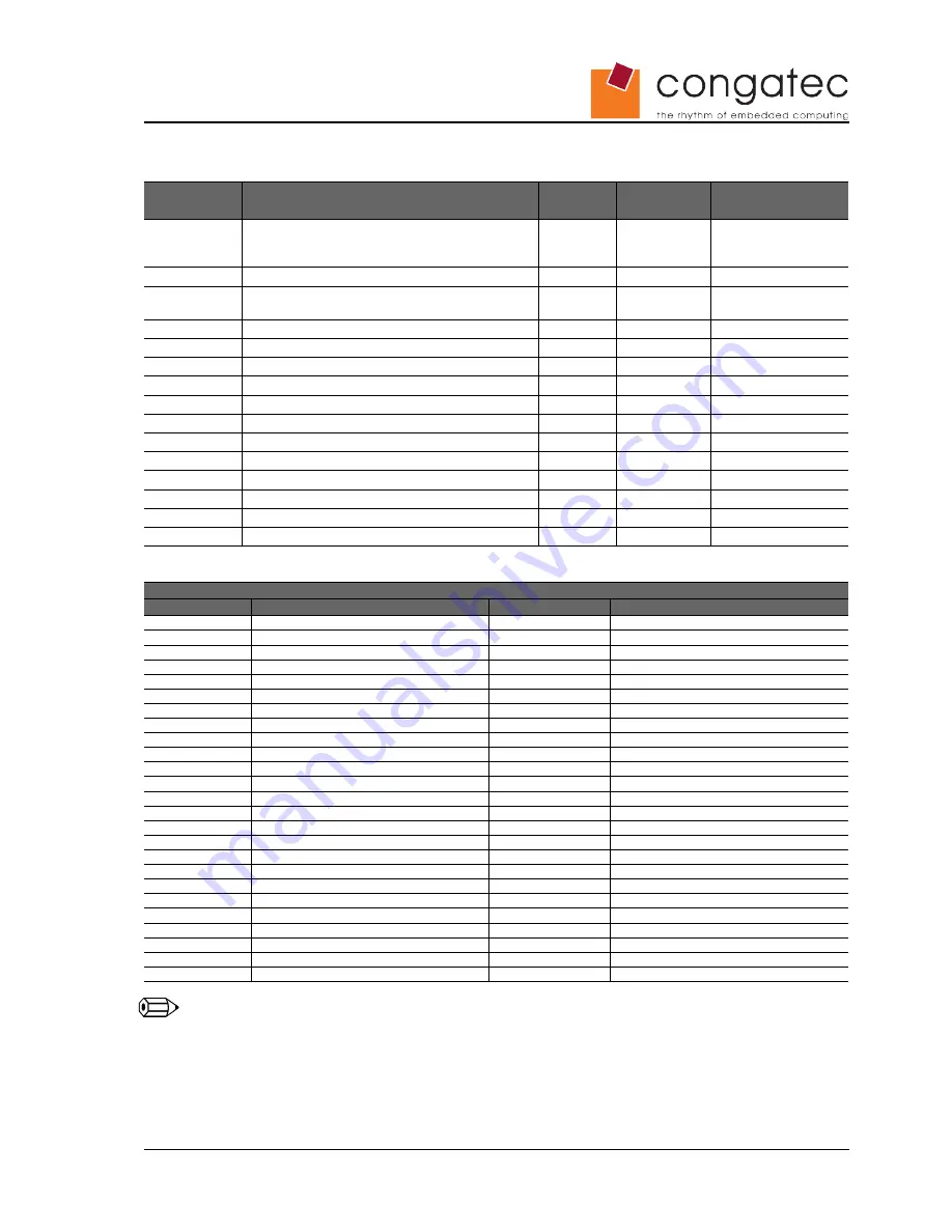
Table 23

FDC Signal Descriptions

Signal

Description of FDC signals (shared with 
LPT)

I/O

PU/PD

Comment

FLPY#

Floppy Interface configuration input

N.A.

Not supported, see 

section 4.3.6 for more 

information.

RES

N.C.

N.A.

Not available

DENSEL

Density select: low = 250/300Kb/s high = 

500/1000Kb/s

O 5V

INDEX#

Index signal

I 5V

TRK0#

Track signal

I 5V

WP#

Write protect signal

I 5V

RDATA#

Raw data read

I 5V

DSKCHG#

Disk change

I 5V

HDSEL#

Head select

O 5V

DIR#

Direction

O 5V

STEP#

Motor step

O 5V

DRV

Drive select

O 5V

MOT#

Motor select

O 5V

WDATA#

Raw write data

O 5V

WGATE#

Write enable

O 5V

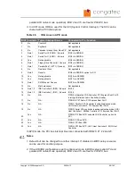
Table 24

Floppy Support Mode Pinout

Floppy Support Mode Pinout

Pin

Signal

Pin

Signal

51

FLPY# (*)

52

RESERVED

53

VCC

54

GND

55

RESERVED

56

DENSEL

57

RESERVED

58

RESERVED

59

IRRX

60

HDSEL#

61

IRTX

62

RESERVED

63

RXD2

64

DIR#

65

GND

66

GND

67

RTS2#

68

RESERVED

69

DTR2#

70

STEP#

71

DCD2#

72

DSKCHG#

73

DSR2#

74

RDATA#

75

CTS2#

76

WP#

77

TXD2

78

TRK0#

79

RI2#

80

INDEX#

81

VCC

82

VCC

83

RXD1

84

DRV

85

RTS1#

86

MOT

87

DTR1#

88

WDATA#

89

DCD1#

90

WGATE#

91

DSR1#

92

MSCLK

93

CTS1#

94

MSDAT

95

TXD1

96

KBCLK

97

RI1#

98

KBDAT

99

GND

100

GND

Note

The   signals   marked   with   an   asterisk   symbol   (*)   are   not   supported   on   the  
conga-X945/XA945.

Copyright © 2006 congatec AG 

X945m13

56/102

Summary of Contents for X945

Page 1: ...XTX conga X945 and conga XA945 Intel Atom N270 Intel Core 2 Duo Intel Core Duo and Celeron M processors with an Intel 945 chipset User s Guide Revision 1 3 ...

Page 2: ...t Removed processor core voltage values from power consumption tables Added caution statement to section 3 Heatspreader 1 2 23 08 07 GDA Changed all references of 82945GM to 82945GME Replaced Intel Core Duo U2500 variant with Intel Core Duo U7500 U2500 is no longer available as a standard variant Added information about center mounting hole to Caution statement in section 3 Heatspreader Added info...

Page 3: ...rticular purpose with regard to any of the foregoing congatec AG assumes no liability for any damages incurred directly or indirectly from any technical or typographical errors or omissions contained herein or for discrepancies between the product and the user s guide In no event shall congatec AG be liable for any incidental consequential special or exemplary damages whether based on tort contrac...

Page 4: ... is permitted without written permission from congatec AG Some of the information found in this user s guide has been extracted WITH EXPRESS PERMISSION from the following COPYRIGHTED American Megatrends Inc documents AMIBIOS8_HDD_Security pdf AMIBIOS8 Flash Recovery Whitepaper pdf AMIBIOS8_SerialRedirection pdf AMIBIOS8 Setup User s Guide The above mentioned documents are Copyright 2005 American M...

Page 5: ...to a defect in materials or workmanship or due to non conformance to the agreed upon specifications will be repaired or exchanged at congatec AG s option and expense Customer will obtain a Return Material Authorization RMA number from congatec AG prior to returning the non conforming product freight prepaid congatec AG will pay for transporting the repaired or exchanged product to the customer Rep...

Page 6: ...ny of the I O interfaces as deemed necessary The baseboard can therefore provide all the interface connectors required to attach the system to the application specific peripherals This versatility allows the designer to create a dense and optimized package which results in a more reliable product while simplifying system integration Most importantly ETX applications are scalable which means once a...

Page 7: ...ariant This user s guide describes all of these options Below you will find an order table showing the different configurations that are currently offered by congatec AG Check the table for the Part no Order no that applies to your product This will tell you what options described in this user s guide are available on your particular module Part No 055874 085691 014781 034571 078965 CPU Intel Core...

Page 8: ... 6 1 CMOS Battery Power Consumption 17 1 7 Environmental Specifications 17 2 Block Diagram 18 3 Heatspreader 19 3 1 Heatspreader Dimensions 20 3 2 Exploded view of Threaded XTX Heatspreader Module and Carrier Board Assembly 21 4 Connector Subsystems 22 4 1 Connector X1 22 4 1 1 PCI Bus 22 4 1 2 USB 22 4 1 3 Audio 23 4 1 4 Onboard Generated Supply Voltage 23 4 2 Connector X2 XTX Extension 24 4 2 1 ...

Page 9: ...ntrol 36 6 5 Thermal Management 39 6 6 ACPI Suspend Modes and Resume Events 40 6 7 USB 2 0 EHCI Host Controller Support 42 7 Signal Descriptions and Pinout Tables 43 7 1 X1 Connector Signal Descriptions 44 7 2 Connector X1 Pinout 46 7 3 X2 Connector Signal Descriptions XTX extension 47 7 4 X2 Connector Pinout 51 7 5 X3 Connector Signal Descriptions 53 7 6 X4 Connector Signal Descriptions 58 7 7 X4...

Page 10: ...nu 87 9 4 10 USB Configuration Submenu 88 9 4 10 1 USB Mass Storage Device Configuration Submenu 89 9 4 11 Keyboard Mouse Configuration Submenu 89 9 4 12 Remote Access Configuration Submenu 90 9 4 13 Hardware Monitoring Submenu 91 9 4 14 Watchdog Configuration Submenu 92 9 5 Boot Setup 93 9 5 1 Boot Device Priority 93 9 5 2 Boot Settings Configuration 94 9 6 Security Setup 95 9 6 1 Security Settin...

Page 11: ... stated by Intel Supports both conventional FPDI and non conventional LDI color mappings Automatic Panel Detection via EPI Embedded Panel Interface based on VESA EDID 1 3 Resolutions 640x480 up to 1600x1200 UXGA Motion Video Support Up and Downscaling High definition content decode H W motion compensation Subpicture support Dynamic bob and weave AUX Output 2 x Intel compliant SDVO ports serial DVO...

Page 12: ...CE 5 0 6 0 Linux QNX 1 3 Mechanical Dimensions 95 0 mm x 114 0 mm 3 75 x 4 5 Height approx 12mm 0 4 1 4 Electrical Characteristics Characteristics Min Typ Max Units Comment 5V Voltage 5 4 75 5 00 5 25 Vdc Ripple 100 mVpp 0 20MHz Current See section 1 5 Power Consumption for supply current information 5V_SB Voltage 5 4 75 5 00 5 25 Vdc Current 250 mA Copyright 2006 congatec AG X945m13 12 102 ...

Page 13: ... PS 2 keyboard and mouse connection and an IDE device connection The baseboard is powered by a Direct Current DC power supply that is set to output 5 Volts and is connected directly to the special baseboard Additionally positive and negative sense lines are connected to the baseboard in order to measure the current consumption of the module This current consumption value is displayed by the DC pow...

Page 14: ...nal Standby Mode requires setup node Suspend Mode in the BIOS to be configured to S1 POS Power On Suspend Suspend to RAM requires setup node Suspend Mode in BIOS to be configured to S3 STR Suspend to RAM Note A software tool was used to stress the CPU to 100 workload Processor Information In the following power tables there is some additional information about the processors Intel offers processor...

Page 15: ...ith 512MB memory installed conga X945 Art No 055874 Intel Core 2 Duo L7400 1 5GHz 4MB L2 cache LV 65nm Layout Rev X945B0 BIOS Rev X945R111 Memory Size 512MB Operating System Windows XP Professional SP2 Power State Desktop Idle 100 workload Standby Suspend to Ram S3 Power consumption measured in Amperes Watts 1 2 A 6 W 5 5 A 27 5 W 1 7 A 8 5 W 0 1 A 0 5 W 1 5 3 conga X945 Intel Core Duo L2400 1 66G...

Page 16: ...orkload Standby Suspend to Ram S3 Power consumption measured in Amperes Watts 1 4 A 7 W 2 5 A 12 5 W 1 4 A 7 W 0 1 A 0 5 W 1 5 6 conga X945 Intel Celeron M 440 1 86GHz 1MB cache With 512MB memory installed conga X945 Art No 078965 Intel Celeron M 440 1 86GHz 1MB L2 cache 65nm Layout Rev X945A0 BIOS Rev X945R111 Memory Size 512MB Operating System Windows XP Professional SP2 Power State Desktop Idle...

Page 17: ...onmental Specifications Temperature Operation 0 to 60 C Storage 20 to 80 C Humidity Operation 10 to 90 Storage 5 to 95 Caution The above operating temperatures must be strictly adhered to at all times When using a heatspreader the maximum operating temperature refers to any measurable spot on the heatspreader s surface congatec AG strongly recommends that you use the appropriate congatec module he...

Page 18: ...2 Block Diagram Copyright 2006 congatec AG X945m13 18 102 ...

Page 19: ...ns may also require that the heatspreader is attached directly to the systems chassis therefore using the whole chassis as a heat dissipater Caution The center mounting hole on the heatspreader must be used to ensure that all components that are required to make contact with heatspreader do so Failure to utilize the center mounting hole will result in improper contact between these components and ...

Page 20: ...3 1 Heatspreader Dimensions Note All measurements are in millimeters Torque specification for heatspreader screws is 0 5 Nm Copyright 2006 congatec AG X945m13 20 102 ...

Page 21: ...3 2 Exploded view of Threaded XTX Heatspreader Module and Carrier Board Assembly Copyright 2006 congatec AG X945m13 21 102 ...

Page 22: ...s The implementation of the PCI bus complies with PCI specification Rev 2 3 and ETX specification Rev 2 7 4 1 2 USB The conga X945 XA945 offers 4 USB ports via the Intel 82801GBM ICH7M that are connected to the X1 connector These ports are both USB 1 1 and 2 0 compliant For more information about how the USB host controllers are routed see section 6 7 Copyright 2006 congatec AG X945m13 22 102 ...

Page 23: ... the X1 connector provide the ability to connect external devices to the modules onboard generated supply voltage 3 3V 5 3 3V external devices can be connected to these pins but must not exceed a maximum external load of 500mA For more information about this feature contact congatec AG technical support Caution Do not connect pins 12 16 and 24 to a 3 3V external power supply This will cause a curr...

Page 24: ...t For more information about how the USB host controllers are routed see section 6 7 4 2 3 Serial ATA Two Serial ATA150 connections are provided via the Intel 82801GBM ICH7M Serial ATA is an enhancement of the parallel ATA therefore offering higher performance As a result of this enhancement the traditional restrictions of parallel ATA are overcome with respect to speed and EMI Serial ATA starts w...

Page 25: ...anagement One of these signals is an output signal called FAN_PWMOUT that allows system fan control using a PWM Pulse Width Modulation Output Additionally there is an input signal called FAN_TACHOIN that provides the ability to monitor the system fan s RPMs revolutions per minute This signal must receive two pulses per revolution in order to produce an accurate reading For this reason a two pulse ...

Page 26: ... is supported on both Display Pipe A and Pipe B 4 3 4 Serial Ports 1 and 2 The conga X945 XA945 offers two serial interfaces TTL that are provided by the Winbond W83627HG Super I O controller located on the conga X945 XA945 4 3 5 Serial Infrared Interface Serial port 2 can be configured as a serial infrared interface The Infrared IrDA function provides point to point or multi point to multi point ...

Page 27: ...4 3 7 Keyboard Mouse The implementation of these subsystems comply with ETX specification 2 7 Copyright 2006 congatec AG X945m13 27 102 ...

Page 28: ...t provides a Fast Mode 400kHz max multi master I C Bus that has maximum I C bandwidth 4 4 4 Power Control PWGIN PWGIN pin 4 on the X4 connector can be connected to an external power good circuit or it may also be utilized as a manual reset input In order to use PWGIN as a manual reset the pin must be grounded through the use of a momentary contact pushbutton switch When external circuitry asserts ...

Page 29: ...This will cause a current cross flow and may result in either a system malfunction and or damage to the external power supply and the module Sometimes when designing baseboards baseboard designers choose to fuse power to some external devices such as keyboards or USB devices by using solid state or polyswitch overcurrent protection devices This results in the protective devices typically only open...

Page 30: ...e visit www formfactors org and view page 25 figure 7 of the document ATX12V Power Supply Design Guide V2 2 4 4 5 Power Management APM 1 2 compliant ACPI 3 0 compliant with battery support Also supports Suspend to RAM S3 Copyright 2006 congatec AG X945m13 30 102 ...

Page 31: ... for most of the congatec BIOS features It fully isolates some of the embedded features such as system monitoring or the I C bus from the x86 core architecture which results in higher embedded feature performance and more reliability even when the x86 processor is in a low power mode 5 3 Embedded BIOS The conga X945 XA945 is equipped with congatec Embedded BIOS and has the following features ACPI ...

Page 32: ...bove diagram provides an overview of how the BIOS Setup Data is backed up on congatec modules OEM default values mentioned above refer to customer specific CMOS settings created using the congatec System Utility tool Copyright 2006 congatec AG X945m13 32 102 ...

Page 33: ...usted Platform Module TPM 1 2 This TPM 1 2 includes co processors to calculate efficient hash and RSA algorithms with key lengths up to 2 048 bits as well as a real random number generator Security sensitive applications like gaming and e commerce will benefit also with improved authentication integrity and confidence levels 5 6 Suspend to RAM S3 The Suspend to RAM feature is available on the cong...

Page 34: ...at it s able to provide more interrupts a total of 24 to be exact It must be mentioned that the APIC is not supported by all operating systems In order to utilize the APIC mode it must be enabled in the BIOS setup program before the installation of the OS and it only functions in ACPI mode You can find more information about APIC in the IA 32 Intel Architecture Software Developer s Manual Volume 3...

Page 35: ...erating temperature Note The maximum operating temperature for Intel Atom Core 2 Duo Core Duo and Celeron M processors is 100 C TM2 mode is used for Intel Atom Core 2 Duo and Core Duo processors it is not supported by Intel Celeron M processors Two modes are supported by the Thermal Monitor to activate the TCC They are called Automatic and On Demand No additional hardware software or handling rout...

Page 36: ...mit the maximum processor frequency This can be useful if the maximum performance is not required or if the maximum processor performance state dissipates too much power and heat In the CPU Configuration submenu of the BIOS Setup Program you ll find the node for Max Frequency limitation For each Intel Core 2 Duo and Core Duo the BIOS lists the supported frequencies If a lower frequency than the ma...

Page 37: ... graphs provide examples of how each maximum frequency limitation setting found in the BIOS Setup Program affects power consumption of the Intel Core Duo processor variants Copyright 2006 congatec AG X945m13 37 102 ...

Page 38: ...Copyright 2006 congatec AG X945m13 38 102 ...

Page 39: ...t having to reduce the overall system performance Use the active cooling trip point setup node in the BIOS setup program to determine the temperature threshold that the operating system will use to start the active cooling device It is stopped again when the temperature goes below the threshold 5 C hysteresis Critical Trip Point If the temperature in the thermal zone reaches a critical point then ...

Page 40: ...e note below on lid button press and wake from Standby see note below on lid button release GPE2 Set GPE2 Function node to Sleep Button in the ACPI setup menu or set Resume On Ring to Enabled in the Power setup menu Onboard LAN Event Device driver must be configured for Wake On LAN support For configuration go to Device Manager Network Adapters Intel R PRO 100 VE Network Connection and launch prop...

Page 41: ...added to re enable it Configure USB keyboard mouse to be able to wake up the system In Device Manager look for the keyboard mouse devices Go to the Power Management tab and check Allow this device to bring the computer out of standby Note When the standby state is set to S3 in the ACPI setup menu the power management tab for USB keyboard mouse devices only becomes available after adding the above ...

Page 42: ...n the conga X945 Within the EHC functionality there is a port routing logic that executes the mixing between the two different types of host controllers EHCI and UHCI This means that when a USB device is connected the routing logic determines who owns the port If the device is not USB 2 0 compliant or if the software drivers for EHCI support are not installed then the UHCI controller owns the port...

Page 43: ...ption tables do not list internal pull ups or pull downs implemented by the chip vendors only pull ups or pull downs implemented by congatec are listed For information about the internal pull ups or pull downs implemented by the chip vendors refer to the respective chip s datasheet Table 2 Signal Tables Terminology Descriptions Term Description PU congatec implemented pull up resistor PD congatec ...

Page 44: ...3 3V PU 8k2 3 3V 5V Tolerant GPERR Bus grant parity error I O 3 3V PU 8k2 3 3V 5V Tolerant PME Bus power management event I O 3 3VSB PU 10k 3 3VSB LOCK Bus lock I O 3 3V PU 8k2 3 3V 5V Tolerant DEVSEL Bus device select I O 3 3V PU 8k2 3 3V 5V Tolerant TRDY Bus target ready I O 3 3V PU 8k2 3 3V 5V Tolerant IRDY Bus initiator ready I O 3 3V PU 8k2 3 3V 5V Tolerant STOP Bus stop I O 3 3V PU 8k2 3 3V ...

Page 45: ...r D I O 3 3V USB 2 0 compliant and backwards compatible to USB 1 1 USB3 USB Port 3 data or D I O 3 3V USB 2 0 compliant and backwards compatible to USB 1 1 USB3 USB Port 3 data or D I O 3 3V USB 2 0 compliant and backwards compatible to USB 1 1 Table 6 Audio Signal Descriptions Signal Description of Audio Signals I O PU PD Comment SNDL Line Level stereo output left O Analog output 1 Vrms SNDR Line...

Page 46: ...RESERVED 67 GND 68 GND 19 VCC 20 VCC 69 AD16 70 CBE2 21 SERIRQ 22 REQ0 71 AD17 72 USB3 23 AD0 24 3V 73 AD19 74 AD18 25 AD1 26 AD2 75 AD20 76 USB0 27 AD4 28 AD3 77 AD22 78 AD21 29 AD6 30 AD5 79 AD23 80 USB1 31 CBE0 32 AD7 81 AD24 82 CBE3 33 AD8 34 AD9 83 VCC 84 VCC 35 GND 36 GND 85 AD25 86 AD26 37 AD10 38 AUXAL 87 AD28 88 USB0 39 AD11 40 MIC 89 AD27 90 AD29 41 AD12 42 AUXAR 91 AD30 92 USB1 43 AD13 ...

Page 47: ...l ATA specification Revision 1 0a SATA1_TX SATA1_TX Serial ATA channel 1 Transmit Output differential pair O SATA Supports Serial ATA specification Revision 1 0a SATA2_RX SATA2_RX Serial ATA channel 2 Receive Input differential pair N C Not supported SATA2_TX SATA2_TX Serial ATA channel 2 Transmit Output differential pair N C Not supported SATA3_RX SATA3_RX Serial ATA channel 3 Receive Input diffe...

Page 48: ...it Output differential pair O PCIE Supports PCI Express Base Specification Revision 1 1 PCIE3_RX PCIE3_RX PCI Express channel 3 Receive Input differential pair I PCIE Supports PCI Express Base Specification Revision 1 1 PCIE3_TX PCIE3_TX PCI Express channel 3 Transmit Output differential pair O PCIE Supports PCI Express Base Specification Revision 1 1 PCIE_CLK_REF PCIE_CLK_REF PCI Express Referenc...

Page 49: ...eset process They may bootstrap some basic important functions of the module For more information refer to section 7 9 of this user s guide AC_SYNC and AC_SDOUT can be used to switch PCI Express channels 0 3 between x1 and x4 mode If both signals are each pulled up using 1k Ω resistors to 3 3V at the rising edge of PWROK then x4 mode is enabled x1 mode is used by default if these resistors are not...

Page 50: ...O 3 3VSB PU 10k 3 3VSB PCI_CLKRUN This clock supports the PCI CLKRUN protocol It connects to peripherals that need to request clock restart or prevention of clock stopping I O 3 3V PU 8k2 3 3V PCI_GNT A reserved O 3 3V PCI_GNT A is a boot strap signal see note below PCI_REQ A reserved I 3 3V PU 8k2 3 3V FAN_PWMOUT Fan speed control Uses the Pulse Width Modulation PWM technique to control the fan s...

Page 51: ...LA17 22 SATA1_TX DACK0 23 EXC1_RST LA18 24 SATA1_TX IRQ14 25 USBP5 LA19 26 GND IRQ15 27 USBP5 LA20 28 SATA2_RX IRQ12 29 GND LA21 30 SATA2_RX IRQ11 31 PCIE2_TX LA22 32 SUS_STAT IRQ10 33 PCIE2_TX LA23 34 PCI_CLKRUN IO16 35 GND GND 36 GND GND 37 PCIE2_RX SBHE 38 SATA2_TX M16 39 PCIE2_RX SA0 40 SATA2_TX OSC 41 EXC0_CPPE SA1 42 GND BALE 43 EXC0_RST SA2 44 SATA3_RX TC 45 USBP4 SA3 46 SATA3_RX DACK2 47 U...

Page 52: ... 80 VCC SMEMR 81 AC_RST IOCHRDY 82 AC_SDOUT AEN 83 VCC VCC 84 VCC VCC 85 AC_SYNC SD0 86 AC_SDIN0 SMEMW 87 AC_SDIN1 SD2 88 AC_SDIN2 SD1 89 AC_BIT_CLK SD3 90 FAN_TACHOIN NOWS 91 LPC_AD0 DREQ2 92 FAN_PWMOUT SD4 93 LPC_AD1 SD5 94 LPC_FRAME IRQ9 95 LPC_AD2 SD6 96 LPC_DRQ0 SD7 97 LPC_AD3 IOCHK 98 LPC_DRQ1 RSTDRV 99 GND GND 100 GND GND Note The signals marked with an asterisk symbol are not supported on ...

Page 53: ...nnel RGB Analog Video Output O PD 150R Analog output G Green channel RGB Analog Video Output O PD 150R Analog output B Blue channel RGB Analog Video Output O PD 150R Analog output DDCK Display Data Channel Clock I O 5V PU 2k2 5V DDDA Display Data Channel Data I O 5V PU 2k2 5V Table 18 TV Signal Descriptions Signal Description of CRT signals I O PU PD Comment SYNC Composite sync N C Not supported Y...

Page 54: ...oot strap signal see note below RTS2 Request to send for COM2 O 5V PD 100k 5V DCD1 DCD2 Data carrier detect for COM1 COM2 I 5V PD 100k 5V DSR1 DSR2 Data set ready for COM1 COM2 I 5V PD 100k 5V Note Some signals have special functionality during the reset process They may bootstrap some basic important functions of the module For more information refer to section 7 9 of this user s guide Table 20 K...

Page 55: ... GND 2 GND 3 R 4 B 5 HSY 6 G 7 VSY 8 DDCK 9 DETECT 10 DDDA 11 LCDDO 16 TX2OUTCLK 12 LCDDO 18 TX2OUT3 13 LCDDO 17 TX2OUTCLK 14 LCDDO 19 TX2OUT3 15 GND 16 GND 17 LCDDO 13 TX2OUT1 18 LCDDO 15 TX2OUT2 19 LCDDO 12 TX2OUT1 20 LCDDO 14 TX2OUT2 21 GND 22 GND 23 LCDDO 8 TX1OUT3 24 LCDDO 11 TX2OUT0 25 LCDDO 9 TX1OUT3 26 LCDDO 10 TX2OUT0 27 GND 28 GND 29 LCDDO 4 TX1OUT2 30 LCDDO 7 TX1OUTCLK 31 LCDDO 5 TX1OUT...

Page 56: ...tor select O 5V WDATA Raw write data O 5V WGATE Write enable O 5V Table 24 Floppy Support Mode Pinout Floppy Support Mode Pinout Pin Signal Pin Signal 51 FLPY 52 RESERVED 53 VCC 54 GND 55 RESERVED 56 DENSEL 57 RESERVED 58 RESERVED 59 IRRX 60 HDSEL 61 IRTX 62 RESERVED 63 RXD2 64 DIR 65 GND 66 GND 67 RTS2 68 RESERVED 69 DTR2 70 STEP 71 DCD2 72 DSKCHG 73 DSR2 74 RDATA 75 CTS2 76 WP 77 TXD2 78 TRK0 79...

Page 57: ... 5V ACK Acknowledge I 5V BUSY Busy I 5V PE Paper empty I 5V SLCT Power On I 5V Table 26 LPT Support Mode Pinout Parallel Port Mode Pinout Pin Signal Pin Signal 51 LPT 52 RESERVED 53 VCC 54 GND 55 STB 56 AFD 57 RESERVED 58 PD7 59 IRRX 60 ERR 61 IRTX 62 PD6 63 RXD2 64 INIT 65 GND 66 GND 67 RTS2 68 PD5 69 DTR2 70 SLIN 71 DCD2 72 PD4 73 DSR2 74 PD3 75 CTS2 76 PD2 77 TXD2 78 PD1 79 RI2 80 PD0 81 VCC 82...

Page 58: ...imary IDE DMA acknowledge O 3 3V PIDE_RDY Primary IDE ready I 3 3V PU 4k7 3 3V 5V tolerant PIDE_IOR Primary IDE IO read O 3 3V PIDE_IOW Primary IDE IO write O 3 3V PIDE_INTRQ Primary IDE interrupt request I 3 3V PU 8k2 3 3V 5V tolerant SIDE_D0 15 Secondary IDE Data bus N C SIDE_A0 2 Secondary IDE Address bus N C SIDE_CS1 Secondary IDE chip select channel0 N C SIDE_CS3 Secondary IDE chip select cha...

Page 59: ... as reset input make low with O C to cause reset 5V_SB Supply of internal suspend circuit P PS_ON Power Save ON O 5VSB PU 10k 5VSB PWRBTN Power Button I 5VSB PU 10k 5VSB Table 31 Power Management Signals Signal Description of Power Management signals I O PU PD Comment RSMRST Resume reset input I 3 3VSB PU 100k 3 3VSB SMBALRT System management bus alert input I 3 3VSB PU 10k 3 3VSB BATLOW Battery l...

Page 60: ... PU 2k2 3 3V SMBDATA SM Bus Data I O 3 3V PU 2k2 3 3V KBINH Keyboard inhibit I 5V OVCR Over current detect for USB I 3 3VSB PU 10k 3 3VSB ROMKBCS Do not connect N A Not available EXT_PRG Do not connect N A Not available GPCS General purpose chip select N C Not supported Note Some signals have special functionality during the reset process They may bootstrap some basic important functions of the mo...

Page 61: ...D3 72 PIDE_D12 23 SMBCLK 24 SMBDATA 73 SIDE_D11 74 PIDE_D3 25 SIDE_CS3 26 SMBALRT 75 SIDE_D4 76 PIDE_D11 27 SIDE_CS1 28 DASP_S 77 SIDE_D10 78 PIDE_D4 29 SIDE_A2 30 PIDE_CS3 79 SIDE_D5 80 PIDE_D10 31 SIDE_A0 32 PIDE_CS1 81 VCC 82 VCC 33 GND 34 GND 83 SIDE_D9 84 PIDE_D5 35 PDIAG_S 36 PIDE_A2 85 SIDE_D6 86 PIDE_D9 37 SIDE_A1 38 PIDE_A0 87 SIDE_D8 88 PIDE_D6 39 SIDE_INTRQ 40 PIDE_A1 89 GPE2 90 CBLID_P...

Page 62: ...ement 6 SDVOC_GREEN Serial Digital Video C green 7 GND Ground 8 SDVOB_BCLKN Serial Digital Video B clock complement 9 SDVOB_BCLKP Serial Digital Video B clock 10 GND Ground 11 SDVOB_GREEN Serial Digital Video B green data complement 12 SDVOB_GREEN Serial Digital Video B green data 13 GND Ground 14 SDVOC_INT Serial Digital Video input interrupt complement 15 SDVOC_INT Serial Digital Video input int...

Page 63: ...tal Video TV Out synchronization clock complement 36 SDVO_TVCLKIN Serial Digital Video TV Out synchronization clock 37 GND Ground 38 SDVOCTRL_CLK I C based control signal Clock for SDVO device 39 SDVOCTRL_DATA I C based control signal Data for SDVO device SDVOCTRL_DATA is a boot strap signal see note below 40 PWRGOOD PWRGOOD signal PU 10k 3 3V 41 5V Power supply 5V 42 5V Power supply 5V 43 5V Powe...

Page 64: ...ot strap signal Pulled high indicates an external SDVO application is present Caution The signals listed in the table above are used as chipset configuration straps during system reset In this condition during reset they are inputs that are pulled to the correct state by either XTX internally implemented resistors or chipset internally implemented resistors that are located on the module No extern...

Page 65: ...2kB 100000 N A N A Extended memory 869kB 1024kB E0000 FFFFF 128kB Runtime BIOS 800kB 869kB D0000 DFFFF 96kB Upper memory 640kB 800kB A0000 CFFFF 160kB Video memory and BIOS 639kB 640kB 9FC00 9FFFF 1kB Extended BIOS data 0 639kB 00000 9FC00 512kB Conventional memory Note T O M Top of memory max DRAM installed VGA frame buffer can be reduced to 1MB in setup Only if ACPI Aware OS is set to YES in set...

Page 66: ...port 0378 037F 8 bytes Note 1 Parallel Port 1 LPT1 03B0 03DF 16 bytes No Video system 03F0 03F5 6 bytes No Floppy channel 1 03F6 1 byte No Primary IDE channel command port 03F7 1 byte No Primary IDE channel status port 03F8 03FF 8 bytes Note 1 Serial Port 1 COM1 0480 04BF 64 bytes No Motherboard resources 04D0 04D1 2 bytes No Motherboard resources 0800 087F 128 bytes No Motherboard resources 0A00 ...

Page 67: ...nter 0 Not applicable 1 No Keyboard Not applicable 2 No Cascade Interrupt from Slave PIC Not applicable 3 Note 1 Serial Port 2 COM2 Generic IRQ3 via SERIRQ 4 Note 1 Serial Port 1 COM1 Generic IRQ4 via SERIRQ 5 Yes Not applicable IRQ5 via SERIRQ 6 Note 1 Floppy Drive Controller Generic IRQ6 via SERIRQ 7 Note 1 Parallel Port 1 LPT1 Generic IRQ7 via SERIRQ 8 No Real time Clock Not applicable 9 Note 3...

Page 68: ...ote 1 2 IDE Controller 0 IDE0 Generic IRQ14 15 Note 1 2 IDE Controller 1 IDE1 Generic IRQ15 16 No N A PIRQA Integrated VGA Controller PCI Express Root Port 0 Intel High Definition Audio Controller Azalia 17 No N A PIRQB AC 97 Audio PCI Express Root Port 1 18 No N A PIRQC Parallel ATA Controller in enhanced native mode UHCI Host Controller 2 PCI Express Root Port 2 19 No N A PIRQD Serial ATA contro...

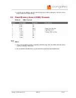
Page 69: ...0 8 bits Yes 1 8 bits Yes 2 8 bits Note 1 Floppy Drive Controller 3 8 bits Note 2 Parallel Port LPT 4 16 bits No Cascade DMA Controller 5 16 bits Yes 6 16 bits Yes 7 16 bits Yes Notes 1 If the corresponding device is disabled in BIOS setup then the DMA channel can be used by customers hardware 2 Not available if Parallel Port is used in ECP mode Enhanced Parallel Port Copyright 2006 congatec AG X9...

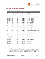
Page 70: ...hanced mode 00h 1Fh 02h Internal Serial ATA Controller in enhanced mode Parallel ATA and Serial ATA as combined IDE Controller in compatible mode 00h 1Fh 03h Internal SMBus Host Controller 01h Note 1 00h xxh Internal PCI Express Port 0 02h Note 1 00h xxh Internal PCI Express Port 1 03h Note 1 00h xxh Internal PCI Express Port 2 04h Note 1 00h xxh Internal PCI Express Port 3 05h Note 1 08h 00h Inte...

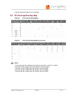
Page 71: ... Root Port 0 PCI EX Root Port 1 PCI EX Root Port 2 PCI EX Root Port 3 PCI EX Port 0 PCI EX Port 1 PCI EX Port 2 PCI EX Port 3 A x x x x 4 x 5 B x x x x 4 x 5 x C x x 4 x 5 x x D x x 5 x x x 4 E x F G H Notes These interrupts are available for external devices slots on the X1 connector Interrupt used by single function PCI Express devices INTA Interrupt used by multifunction PCI Express devices INT...

Page 72: ...red PCI devices can not be guaranteed 8 8 I C Bus There are no onboard resources connected to the I C bus Address 16h is reserved for congatec Battery Management solutions 8 9 SM Bus System Management SM bus signals are connected to the Intel I O Controller Hub 82801GBM ICH7M and the SM bus is not intended to be used by off board non system management devices For more information about this subjec...

Page 73: ...epeatedly immediately after power is initiated will result in the manufacturer default settings being loaded for that boot sequence and only that boot sequence This is helpful when a previous BIOS setting is no longer desired If you want to change the BIOS settings or save the manufacturer default settings then you must enter the BIOS setup program and use the Save and Exit function This feature i...

Page 74: ...ocessor memory and board information and is for configuring the system date and time Feature Options Description System Time Hour Minute Second Specifies the current system time Note The time is in 24 hour format System Date Day of week month day year Specifies the current system date Note The date is in month day year format BIOS ID no option Displays the BIOS ID Processor no option Displays the ...

Page 75: ...ed Boot Security Power Exit ACPI Configuration PCI Configuration Graphics Configuration CPU Configuration Chipset Configuration I O Interface Configuration Clock Configuration IDE Configuration USB Configuration Keyboard Mouse Configuration Remote Access Configuration Hardware Health Configuration Watchdog Configuration Copyright 2006 congatec AG X945m13 75 102 ...

Page 76: ... C Specifies the temperature threshold at which the ACPI aware OS turns the fan on off Passive Cooling Trip Point Disabled 50 60 70 80 90 C Specifies the temperature threshold at which the ACPI aware OS starts stops CPU clock throttling Critical Trip Point Disabled 80 85 90 95 100 105 110 C Specifies the temperature threshold at which the ACPI aware OS performs a critical shutdown Watchdog ACPI Ev...

Page 77: ... failure there are three check boxes that define what Windows will do when a fatal error has been detected In order to ensure that the system restarts after a Watchdog ACPI Event that is set to Restart you must make sure that the check box for the selection Automatically restart has been checked If this option is not selected then Windows will remain at a blue screen after a Watchdog ACPI Event th...

Page 78: ... PCI Interrupt Routing sub menu Opens PCI Interrupt Routing sub menu 9 4 2 1 PCI IRQ Resource Exclusion Submenu Feature Options Description IRQ xx Available Reserved Allow or restrict the BIOS from giving IRQ resource to PCI PNP devices Note Assigned IRQ resources are shaded and listed as Allocated 9 4 2 2 PCI Interrupt Routing Submenu Feature Options Description PIRQ xx devices Auto 3 4 14 15 Sel...

Page 79: ... SDVO B LFP Select order in which devices are checked and enabled as boot display devices in case a combination of LFP and SDVO devices is present The preference selection is only used if Boot Display Device selection is set to Auto Always Try Auto Panel Detect No Yes If set to Yes the BIOS will first look for an EDID data set in an external EEPROM to configure the Local Flat Panel Only if no exte...

Page 80: ...og Select the SDVO device connected to this port SDVO DVI Hotplug Support Disabled Enabled If set to Enabled the Windows XP 2000 Vista graphics drivers will support hotplug of DVI monitors connected to a DVI SDVO transmitter This means that a DVI monitor connected while the Windows XP 2000 Vista system is already running will automatically be detected and added to the output display device list Di...

Page 81: ... option is not available for Celeron M CPUs Max CPU Frequency Available options depend on processor Allows to reduce the maximum processor frequency This limits the maximum frequency the CPU can be set to when SpeedStep is set to Automatic or Maximum Speed Used when the system is AC powered Note This option is not available for Celeron M CPUs Max CPU Frequency Battery same as above Allows to reduc...

Page 82: ... Limiting the CPUID input value may be required for older operating systems that cannot handle the extra CPUID information returned when using the full CPUID input value Execute Disable Bit Disabled Enabled Enable or disable the hardware support for data execution prevention Intel SpeedStep tech Enabled Disabled Enabled CPU speed is controlled by the operating system Disabled No SpeedStep default ...

Page 83: ...imer can be used for precise multimedia or real time application timing Special software support is required HPET Memory Address FED00000h FED01000h FED02000h FED03000h Set the high precision event timer memory base address IOAPIC Disabled Enabled Enable Disable ICH7M IOAPIC function APIC ACPI SCI IRQ Disabled Enabled If set to Disabled IRQ9 is used for the SCI If set to Enabled IRQ20 is used for ...

Page 84: ...able memory to reserve for each enabled but empty PCI Express slot PCIE Port 0 IOxAPIC Enable Disabled Enabled Enable support for IOAPIC behind PCI Express port PCIE Port 0 IOxAPIC Enable Disabled Enabled Enable support for IOAPIC behind PCI Express port PCIE Port 0 IOxAPIC Enable Disabled Enabled Enable support for IOAPIC behind PCI Express port PCIE Port 0 IOxAPIC Enable Disabled Enabled Enable ...

Page 85: ...guration Disabled 3F8 IRQ4 2F8 IRQ3 3E8 IRQ4 2E8 IRQ3 Specifies the I O base address and IRQ of serial port 1 2 Serial Port 2 Mode Normal IrDA ASK IR Specifies the mode for serial port 2 IR Duplex Mode Full Duplex Half Duplex Select IRDA full or half duplex function IR I O Pin Select SINB SOUTB IRRX RTX Select receiver and transmit pins for IRDA mode Parallel Port Address Disabled 378 278 3BC Spec...

Page 86: ...ry IDE Master sub menu Reports type of connected IDE device Primary IDE Slave sub menu Reports type of connected IDE device Secondary IDE Master sub menu Reports type of connected IDE device Secondary IDE Slave sub menu Reports type of connected IDE device Hard Disk Write Protect Disabled Enabled If enabled protects the hard drive from being erased Disabled allows the hard drive to be used normall...

Page 87: ... other types of IDE disk drives ARMD specifies an ATAPI Removable Media Device This includes but is not limited to ZIP and LS 120 LBA Large Mode Disabled Auto Set to AUTO to let the BIOS auto detect LBA mode control Set to Disabled to prevent the BIOS from using LBA mode Block Multi Sector Transfer Disabled Auto Set to AUTO to let the BIOS auto detect device support for multi sector transfer The d...

Page 88: ...able Disable USB keyboard legacy support NOTE This option has to be used with caution If the system is equipped with USB keyboard only then the user cannot enter setup to enable the option back USB Mouse Legacy Support Disabled Enabled Enable Disable USB mouse legacy support USB Storage Device Support Disabled Enabled Enable Disable USB mass storage device support Port 64 60 Emulation Disabled Ena...

Page 89: ...isk CDROM assumes the CD ROM is formatted as bootable media specified by the El Torito Format Specification 9 4 11 Keyboard Mouse Configuration Submenu Feature Options Description Bootup Num Lock Off On Specifies the power on state of the Num lock feature on the numeric keypad of the keyboard Typematic Rate Slow Fast Specifies the rate at which the computer repeats a key that is held down Slow set...

Page 90: ...ity is disabled at the end of BIOS POST If set to Always all resources and interrupts associated with Serial Redirection are protected and not released to DOS This option lets Serial Redirection permanently reside at base memory which allows the DOS console to be redirected Note that graphics output VGA SVGA etc from DOS programs is not redirected If set to Boot loader Serial Redirection is active...

Page 91: ...no option Current processor die temperature DIMM Environment Temperature no option Current environment temperature of the DIMM Fan1 Speed no option Current FAN speed VcoreA no option Current Core A reading VcoreB no option Current Core B reading 3 3Vin no option Current 3 3V reading 5Vin no option Current 5V reading 5VSB no option Current 5V standby reading VRTC no option Current VRTC reading Copy...

Page 92: ...e then the watchdog will be disabled If set to Repeated event the last stage will be executed repeatedly until a reset occurs Delay see Post Watchdog Select the delay time before the runtime watchdog becomes active This ensures that an operating system has enough time to load Event 1 NMI ACPI Event Reset Power Button Selects the type of event that will be generated when timeout 1 is reached For mo...

Page 93: ...evices are physically removed or added to the system The Type Based boot menu is static and can only be changed by the user 1st 2nd 3rd Boot Device Up to 12 boot devices can be prioritized if device based priority list control is selected If Type Based priority list control is enabled only 8 boot devices can be prioritized Disabled Primary Master Primary Slave Secondary Master Secondary Slave Lega...

Page 94: ...as to be rebooted in order for the Intel Boot Agent device to be available in the Boot Device Menu Power Loss Control see note below Remain Off Turn On Last State Specifies the mode of operation if an AC power loss occurs Remain Off keeps the power off until the power button is pressed Turn On restores power to the computer Last State restores the previous power state before power loss occurred No...

Page 95: ...f the hard disk drive If enabled the following appears when a write is attempted to the boot sector You may have to type N several times to prevent the boot sector write Boot Sector Write Possible VIRUS Continue Y N The following appears after any attempt to format any cylinder head or sector of any hard disk drive via the BIOS INT13 hard disk drive service Format Possible VIRUS Continue Y N HDD S...

Page 96: ...on Primary Secondary Master Slave HDD User Password enter password Set or clear the user password for the hard disk Note This option will be shaded if the hard drive does support the Security Mode Feature set but user failed to unlock the drive during BIOS POST 9 6 2 2 Hard Disk Security Master Password Feature Options Description Primary Secondary Master Slave HDD Master Password enter password S...

Page 97: ...red Device Ignore Monitor Determines whether the device activity is monitored by the power management timer or not Resume On Ring Disabled Enabled Disable enable RI signal GPE2 on pin 89 of X4 connector to generate a wake event If enabled wake is possible from all power down states including S5 Soft Off Resume On PME Disabled Enabled Disable enable PCI PME to generate a wake event If enabled wake ...

Page 98: ... Exit setup and reboot so the new system configuration parameters can take effect Discard Changes and Exit Exit setup without saving any changes made in the BIOS setup program Discard Changes Discard changes without exiting setup The option values presented when the computer was turned on are used Load CMOS Defaults Load the CMOS defaults of all the setup options Copyright 2006 congatec AG X945m13...

Page 99: ...ore information about Updating the BIOS refer to the user s guide for the congatec System Utility which is called CGUTLm1x pdf and can be found on the congatec AG website at www congatec com 10 2 BIOS Recovery The BIOS recovery scenario is recommended for situations when the normal flash update fails and the user can no longer boot back to an OS to restore the system The code that handles BIOS rec...

Page 100: ...oth a supervisor and user password If you use both passwords the supervisor password must be set first The system can be configured so that all users must enter a password every time the system boots or when setup is executed The two passwords activate two different levels of security If you select password support you are prompted for a one to six character password Type the password on the keybo...

Page 101: ...endently however the drive will only lock if a user password is installed The max length of the passwords is 32 bytes During POST each hard drive is checked for security mode feature support In case the drive supports the feature and it is locked the BIOS prompts the user for the user password If the user does not enter the correct user password within five attempts the user is notified that the d...

Page 102: ... Universal Serial Bus USB Specification Revision 2 0 http www usb org home PCI Specification Revision 2 2 http www pcisig com specifications PCI Express Base Specification Revision 1 0a http www pcisig com specifications Serial ATA Specification Revision 1 0a http www serialata org Advanced Configuration and Power Interface Specification Revision 2 0c August 25 2003 http www acpi info Information ...

Reviews: