Table of Contents
Page
i
1.0
INTRODUCTION
1.1
Intended Use . . . . . . . . . . . . . . . . . . . . . . . . . . . . . . . . . . . . . . . . . . . . . . . . . . . . . . . . . 1
1.2
Warnings and Cautions . . . . . . . . . . . . . . . . . . . . . . . . . . . . . . . . . . . . . . . . . . . . . . . . . 1
1.2.1
Warnings . . . . . . . . . . . . . . . . . . . . . . . . . . . . . . . . . . . . . . . . . . . . . . . . . . . . . 1
1.2.2
Cautions . . . . . . . . . . . . . . . . . . . . . . . . . . . . . . . . . . . . . . . . . . . . . . . . . . . . . . 2
1.3
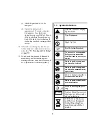
Symbol Definitions . . . . . . . . . . . . . . . . . . . . . . . . . . . . . . . . . . . . . . . . . . . . . . . . . . . . 3
1.4
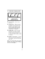
MicroPower High Speed Drill . . . . . . . . . . . . . . . . . . . . . . . . . . . . . . . . . . . . . . . . . . . 4
1.5
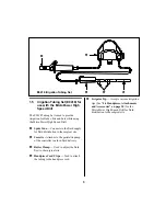
Irrigation Tubing Set (E9418) for use with the MicroPower High Speed Drill . . . . . . 5
2.0
HANDPIECE INSTALLATION and OPERATION
2.1
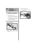
Handpiece Cord Installation . . . . . . . . . . . . . . . . . . . . . . . . . . . . . . . . . . . . . . . . . . . . . 6
2.2
Hall Bur Guard Assembly Instructions. . . . . . . . . . . . . . . . . . . . . . . . . . . . . . . . . . . . . 7
2.2.1
Assembly Instructions for the Medium Bur Guard (1375-012),
Long Bur Guard (1375-011), Cloward Extra-Long Bur Guard (1375-023),
Tissue Retractor Guard (1387-022) . . . . . . . . . . . . . . . . . . . . . . . . . . . . . . . . . 8
2.2.2
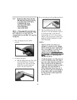
Assembly Instructions for the Laminectomy Bur Guard (1375-020) . . . . . . 10
2.2.3
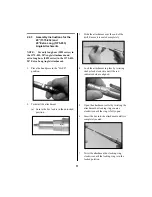
Assembly Instructions for the 20° (1375-032) and 20° Extra Long
(1375-033) Angle Attachments . . . . . . . . . . . . . . . . . . . . . . . . . . . . . . . . . . . 11
2.2.4
Assembly Instructions for the 70° Contra-Angle with Surgical
Head (1375-034), 70° Contra-Angle with Dental Head (1375-035),
90° Angle (1375-036) Attachments . . . . . . . . . . . . . . . . . . . . . . . . . . . . . . . . 12
2.3
Handpiece Operation . . . . . . . . . . . . . . . . . . . . . . . . . . . . . . . . . . . . . . . . . . . . . . . . . 13
2.3.1
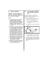
Tubing Set Attachment (E9418) for the MicroPower High Speed Drill . . . . 13
2.3.2
Preoperative Functional Test for the MicroPower High Speed Drill . . . . . . 14
2.3.3
High Speed Drill Attachments and Accessories . . . . . . . . . . . . . . . . . . . . . . 15
2.3.4
Removing the Detachable Handpiece Activation Lever . . . . . . . . . . . . . . . . 16
2.4
Footswitch Operation . . . . . . . . . . . . . . . . . . . . . . . . . . . . . . . . . . . . . . . . . . . . . . . . . 17
2.4.1
Operation of the 2-Pedal Footswitch (5020-053) . . . . . . . . . . . . . . . . . . . . . 17
2.4.2
Operation of the 3-Pedal Footswitch (C9863) . . . . . . . . . . . . . . . . . . . . . . . . 17
2.5
Handpiece Cord Button Operation . . . . . . . . . . . . . . . . . . . . . . . . . . . . . . . . . . . . . . . 18
Summary of Contents for Hall MicroPower 6020-026
Page 1: ...Hall MicroPower High Speed Drill Instruction Manual 6020 026 6021 026 ...
Page 36: ...32 ...
Page 37: ...33 ...
Page 38: ...34 ...
Page 39: ......


