R
1-5
• High voltages are developed within the unit
that are accessible when the top cover is removed.
These voltages are potentially dangerous and
should be treated with extreme caution.
• The high voltage dc power supply in the Sabre
2400 is equipped with a bleeder resistor to dis-
sipate the charge on the filter capacitor. When the
red L.E.D. on the A1 Power/Output Board is lit,
high voltage is present, and caution must be used
during servicing.
• Never remove or install any parts with power
on.
• Avoid contact with the output leads when the
unit is activated. Periodically inspect the test
leads used for the output connections for obvious
defects.
• Although this unit will withstand momentary
short circuits on the output, prolonged short cir-
cuits may damage the unit. Short circuiting the
output should be avoided since it is neither neces-
sary nor desirable.
• Since the clinical use of electrosurgical units
is intermittent in nature with duty cycles on the
order of 10%, this unit is not designed to operate
for extended periods of continuous output. When
testing, it is recommended that duty cycles be
limited to 15 seconds on, 30 seconds idle.
• Life of the equipment will be extended by
minimizing operating temperature and extreme
thermal cycles.
• The heat dissipation capability of the heat sink
is severely impaired by activating the Sabre 2400
in other than its normal operating position. There
are no tests requiring operation in any other posi-
tion.
• Consult the factory for advice before making
any modifications to the unit.
• Ensure that the two top cover screws are tight-
ened before returning the unit to service.
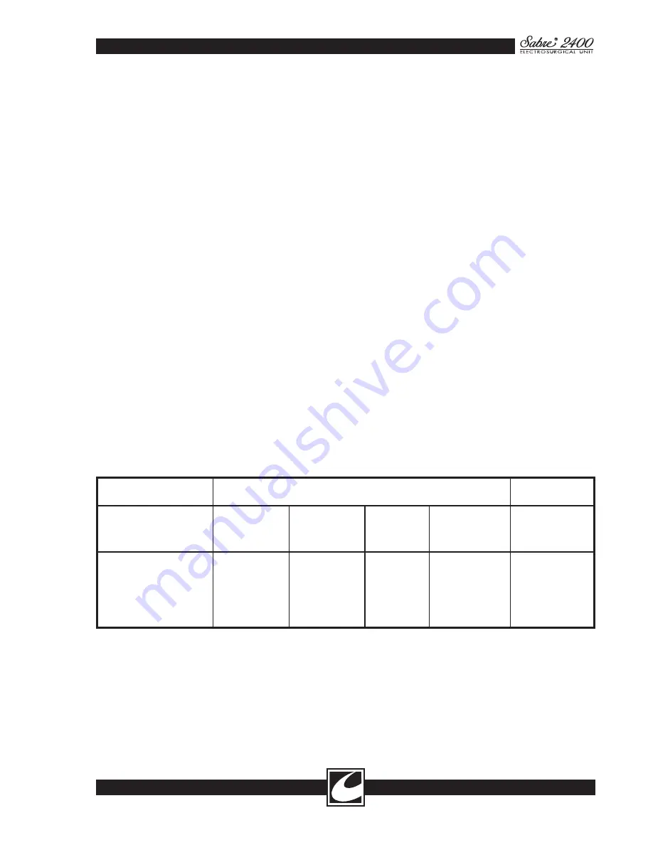
1.2 SPECIFICATIONS
Mains Voltage
Mains Current
VRMS
ARMS
Catalog Number
Nominal
Minimum
Maximum
Nominal Idle
Maximum
Nominal line
(Cut 300W)
60-5600-002
120
104
127
0.8
7.0
60-5600-003
100
90
110
1.0
8.4
60-5600-004
220
198
242
0.5
3.8
60-5600-005
240
216
264
0.4
3.5
60-5600-015
230-240
207
264
0.5
3.7
INPUT POWER (All Units 700W max 50/60 Hz)
Classifications: IEC 601-2-2, Class 1
IEC 601-1-2
Summary of Contents for Sabre 2400
Page 1: ...Operator Service Manual R ...
Page 6: ...R This page intentionally left blank ...
Page 16: ...R 1 10 Figure 1 2 Blend Cut Load Regulation Figure 1 3 Monopolar Coagulation Load Regulation ...
Page 18: ...R 1 12 This page intentionally left blank ...
Page 41: ...R 3 13 Figure 3 2 Waveform Generator Output ...
Page 42: ...R 3 14 Figure 3 3 RF Output Waveforms ...
Page 43: ...R 3 15 Figure 3 3 RF Output Waveforms ...


