R
2-8
2.5 OPERATING INSTRUCTIONS
2.5.1 Preliminary Set Up
1. Ensure the Power Switch is OFF, then con-
nect the power cable to a properly grounded and
polarized mating power receptacle. Do not con-
nect a Return electrode at this time.
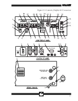
2. Set the Power Switch to the ON position. The
green lamp in the Power Switch shall illuminate.
Within one second, the machine should respond
by:
a) Sounding each of the four tones in ascending
order over a 1 second interval.
b) During that interval, displaying a total of nine
“8”s on the four digital displays.
c) Illuminating all four mode indicators, all selec-
tion indicators, and all of the Resistance Indicator
bars.
d) After the fourth tone is complete, the machine
should beep the highest frequency tone twice, and
light the Return Monitor. A single zero should
appear in each of the four digital displays. If
the unit is in Single Pad Mode, the Resistance
Indicator should be extinguished. If the unit is in
the Dual Pad Mode, the Resistance Indicator bars
will continuously flash.
After two seconds, the unit is ready for use. If the
unit sounds a continuous high tone, or otherwise
fails to respond as above, the unit has failed one
of its internal tests and is not suitable for use.
Before turning the power off, note the “HLP”
code displayed in the Power Displays to assist in
the diagnosis by a biomedical technician.
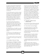
3. Inspect, then connect the desired monopolar
accessories to the hand controlled or foot switch
controlled connectors of the unit. Refer to Figure
2.2 for typical monopolar accessory connections.
Connect the desired foot switchable bipolar acces-
sory to the two blue bipolar banana jacks. (Refer
to Figure 2.2). If a hand switchable bipolar acces-
sory is to be used, connect the RF lines to the
two blue jacks with the switch connected between
the black jack and the bottom blue jack.
>WARNING<
ALWAYS STOW UNUSED ACCESSORIES
IN A SAFE, INSULATED LOCATION
SUCH AS A HOLSTER.
4. Connect the foot switches, as required, to the
rear of the unit (not required if only hand switch-
able accessories are to be used).
5. Inspect, then connect the plug of the dispersive
electrode cable to the return electrode jack or to
an appropriate adapter. Refer to Figure 2.2. A
dispersive electrode need not be connected if only
Bipolar operation is required.
NOTE: This electrosurgical unit incorporates the
Aspen Return Monitor. The monitor will inhibit
monopolar operation of the unit if its require-
ments for the return electrode have not been satis-
fied (see instruction 7).
6. Select and prepare the patient return electrode
site and apply the return electrode in accor-
dance with the manufacturer's instructions. If no
instructions are given, observe the guidelines pro-
vided in Section 1 of this manual.
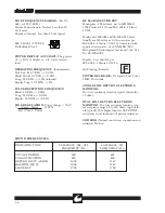
7. Use the RETURN MONITOR buttons to
select DUAL or SINGLE Pad Mode. Confirm
that the Resistance Indicator and the RETURN
MONITOR Indicator are blank if SINGLE pad
mode is selected. If DUAL pad mode is selected,
press the MONITOR SET key. Confirm the
RETURN MONITOR indicator is dark, and the
Resistance Indicator stops flashing and displays
2 to 8 bars. The number of bars indicates the
patient's resistance and can be used as an indica-
tor of patient risk. See Figure 3.1 for the patient
resistance vs. Resistance Indicator bar graph.
Summary of Contents for Sabre 2400
Page 1: ...Operator Service Manual R ...
Page 6: ...R This page intentionally left blank ...
Page 16: ...R 1 10 Figure 1 2 Blend Cut Load Regulation Figure 1 3 Monopolar Coagulation Load Regulation ...
Page 18: ...R 1 12 This page intentionally left blank ...
Page 41: ...R 3 13 Figure 3 2 Waveform Generator Output ...
Page 42: ...R 3 14 Figure 3 3 RF Output Waveforms ...
Page 43: ...R 3 15 Figure 3 3 RF Output Waveforms ...

