R
2-9
>WARNING<
DO NOT DEPEND SOLELY ON
THE RESISTANCE INDICATOR
FOR CONFIRMATION OF GOOD
RETURN ELECTRODE APPLICATION.
QUALIFIED PERSONNEL SHOULD
MAKE THE FINAL DECISION ON
PROPER ELECTRODE PLACEMENT.
8. Set the Monopolar Cut Mode to Pure for
cutting with minimum hemostasis, or Blend
for moderate cutting hemostasis. The mode is
changed by pressing the PURE or BLEND but-
tons. The selected mode is indicated by the back-
lighting of the PURE or BLEND button.
9. Adjust the CUT, COAG, and BIPOLAR
power level controls to the desired levels. If
unsure of the proper settings, use low power
settings initially and make adjustments intraop-
eratively according to the surgeon's requests. A
written record of each surgeon’s preferred power
setting for various procedures will expedite subse-
quent pre-op setup.
In case of an internal failure, the Sabre 2400 will
emit a loud tone to indicate that it has shut itself
down. A visual HLP Code is then displayed on
the Cut and Coag power indicator displays. The
HLP code should be recorded and reported to
Bioengineering. Repairs will be necessary before
returning the unit to service unless the fault con-
dition was transient in nature. Refer to Section 4
for a list of HLP (HELP) codes and their mean-
ings. This alarm is silenced only by turning off
the power switch.
2.5.2 Operation
Activate the electrosurgical unit in the desired
operating mode by depressing the appropriate
treadle of the foot switch or switch of a hand
accessory. Adjust the corresponding power level
control until the desired results are obtained. The
available power in watts will be displayed on the
digital display corresponding to activation mode.
Noting this wattage may be useful in attempt-
ing to derive similar surgical effects from several
machines of different manufacturers. The surgi-
cal effects obtained are dependent on a number
of factors including waveform, electrode size,
electrode geometry, power level and surgical tech-
nique.
The size and geometry of monopolar electrodes
are significant in that a large electrode, absent of
sharp features (e.g., a ball electrode) will have
no tendency to cut, regardless of the waveform
power level. Conversely, a small, sharp electrode,
such as a needle or wire loop, will be likely to
cut simply from mechanical pressure. Therefore,
when coagulating with small geometry electrodes,
it is advisable to use only coagulation waveforms,
use little if any mechanical pressure, and operate
with lower power levels.
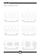
The waveform is selected by the user via hand or
foot switch and the setting of the active Mode
switches. Cutting waveforms are generally contin-
uous (Pure) or high duty cycles with wide pulse
widths (Blend). Monopolar Coagulation wave-
forms are generally of narrow pulse widths with
very low duty cycles. In general, the lower the
duty cycle, the less tendency a waveform will have
to cut and the greater its tendency to coagulate.
The Bipolar Coagulation waveform is designed to
minimize tissue sticking and popping by limiting
the output voltage regardless of power setting.
Bipolar hemostasis is more localized than that in
monopolar, since only the tissue grasped between
the forceps tips is affected. This is particularly
desirable in vascular surgery, where monopolar
current may concentrate in the affected vessel
resulting in undesired electrosurgical effects in
tissue remote from the point of application. This
easily controlled localization is also of benefit in
plastic and neurosurgery.
Summary of Contents for Sabre 2400
Page 1: ...Operator Service Manual R ...
Page 6: ...R This page intentionally left blank ...
Page 16: ...R 1 10 Figure 1 2 Blend Cut Load Regulation Figure 1 3 Monopolar Coagulation Load Regulation ...
Page 18: ...R 1 12 This page intentionally left blank ...
Page 41: ...R 3 13 Figure 3 2 Waveform Generator Output ...
Page 42: ...R 3 14 Figure 3 3 RF Output Waveforms ...
Page 43: ...R 3 15 Figure 3 3 RF Output Waveforms ...


