R
3-10
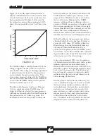
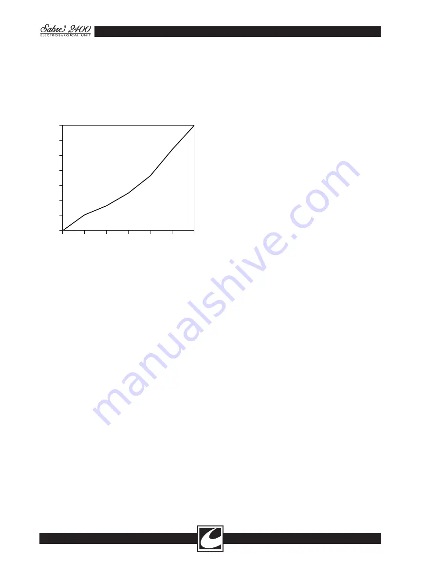
Figure 3.1 shows the approximate resistance vs.
number of illuminated bars in the resistance indi-
cator. If no bars are lit, then the resistance is less
than approximately 10 ohms, if 10 bars are lit,
the resistance is greater than approximately 150
ohms. It is not possible for just 1 or 9 bars to be
lit.
In Dual Foil Mode, the Resistance Indicator will
be illuminated to indicate pad resistance in the
range of 10 to 150 ohms. At just over 10 ohms,
the two left bars are illuminated. As VARM
increases, additional bars are illuminated in pro-
portion to VARM, progressing to the right, until
the resistance approaches 150 ohms, where eight
bars are illuminated. When resistance exceeds 150
ohms, all ten bars are illuminated. Whenever a
Return Fault condition exists, all illuminated bars
will flash, but resistance is still displayed as above.
In Dual Foil Mode, the microprocessor declares
a Return Fault if R
LOAD
is less than 10 ohms or
greater than 150 ohms. If VARM is within the
allowed range, then the Return Fault Indicator
will turn off when the Monitor Set Key is
pressed, and the present value of VARM is stored
for reference. A new Return Fault will be declared
if pad resistance rises about 20% above this stored
value or goes out of the allowed range.
A rise of approximately 20% over the resistance
of a Return electrode in full contact with a patient
indicates significant electrode detachment. A
Return Fault declared in this case will NOT auto-
matically be cleared if the patient resistance drops
back to near the stored value. The Monitor Set
Key must again be pressed to register the staff's
satisfaction that the electrode attachment is safe
before turning off the alarm.
Because patients’ and return site resistances vary
over a considerable range, it is not safe to assume
that any in-range resistance indicates safe elec-
trode attachment. For example, a poorly placed
electrode on a well-perfused site can show the
same resistance as a safely attached electrode on
adipose tissue. Yet the poorly placed electrode
could still result in a burn due to low contact
area. The clinical staff is responsible for the final
judgement of safe return electrode placement.
FIGURE 3.1
The VARM voltage is read by channel #0 of the
analog to digital converter (A2U16) to an accu-
racy of 10mv. This voltage is directly proportional
to pad resistance and is used by the program to
test and display the pad resistance value. This
value is then processed along with the VARM val-
ues for 10 and 150 ohm return circuit resistances
stored in the EEPROM during the last pad cali-
bration to evaluate the current.
The Return Fault process works on a 50-point
(0.6 sec) minimum average VARM value. If
Single Foil Mode is selected, the microprocessor
will declare a Return Fault when VARM indicates
that pad resistance is 10 ohms or greater. The
Resistance Indicator is always dark in this mode.
150
130
110
90
70
50
30
10
2
4
6
8
RESISTANCE (OHMS)
RESISTANCE BARS
Summary of Contents for Sabre 2400
Page 1: ...Operator Service Manual R ...
Page 6: ...R This page intentionally left blank ...
Page 16: ...R 1 10 Figure 1 2 Blend Cut Load Regulation Figure 1 3 Monopolar Coagulation Load Regulation ...
Page 18: ...R 1 12 This page intentionally left blank ...
Page 41: ...R 3 13 Figure 3 2 Waveform Generator Output ...
Page 42: ...R 3 14 Figure 3 3 RF Output Waveforms ...
Page 43: ...R 3 15 Figure 3 3 RF Output Waveforms ...


